Rotating shaft of desk lamp

A technology for a rotating shaft and a table lamp, applied in the field of table lamp parts, can solve the problems of inconvenient installation and adjustment of the damping of the rotating shaft, difficult wiring of the rotating shaft of the table lamp, complicated structure of the rotating shaft, etc., and achieves the effect of avoiding the risk of exposure, simple structure and high threading efficiency.

Pending Publication Date: 2020-11-03
CHONGQING SILIAN OPTOELECTRONICS SCI & TECH
View PDF0 Cites 1 Cited by
  • Summary
  • Abstract
  • Description
  • Claims
  • Application Information

AI Technical Summary

Problems solved by technology

[0003] In view of the above-mentioned shortcomings of the prior art, the object of the present invention is to provide a desk lamp shaft, which is used to solve the problems of difficult wiring inside the desk lamp shaft, complicated shaft structure, inconvenient installation and adjustment of damping between the shafts, and high cost in the prior art. question

Method used


Image

  • Rotating shaft of desk lamp
  • Rotating shaft of desk lamp
  • Rotating shaft of desk lamp

Examples


Embodiment Construction

[0045] Embodiments of the present invention are described below through specific examples, and those skilled in the art can easily understand other advantages and effects of the present invention from the content disclosed in this specification. The present invention can also be implemented or applied through other different specific implementation modes, and various modifications or changes can be made to the details in this specification based on different viewpoints and applications without departing from the spirit of the present invention.

[0046] It should be noted that terms such as "upper", "lower", "left", "right", "middle" and "one" quoted in this specification are only for the convenience of description and are not intended to be used. To limit the practicable scope of the present invention, the change or adjustment of the relative relationship shall also be regarded as the practicable scope of the present invention without substantially changing the technical conte...


PUM


Abstract

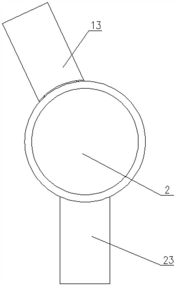
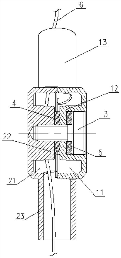
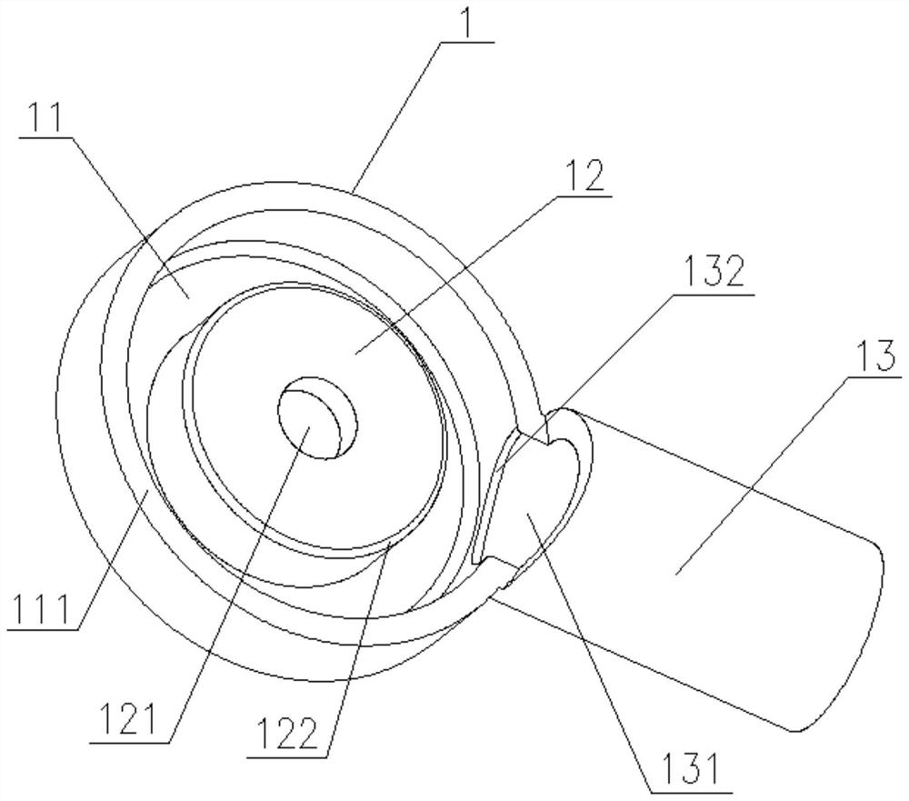
The invention relates to the technical field of desk lamp parts, in particular to a rotating shaft of a desk lamp which comprises a first rotating shaft body, a second rotating shaft body and a locking piece, a first wire groove is concavely formed in one end of the first rotating shaft body, a first wiring pipe is arranged on the outer side wall of the first rotating shaft body, and a first threading hole communicating with the first wire groove is formed in the first wiring pipe; a rotating shaft cathode is convexly arranged in the first wire groove; a second wire groove is concavely formedin one end of the second rotating shaft body, a second wiring pipe is arranged on the outer side wall of the second rotating shaft body, a second threading hole communicating with the second wire groove is formed in the second wiring pipe, a rotating shaft anode corresponding to the rotating shaft cathode is convexly arranged in the second wire groove, and a damping piece is arranged between the rotating shaft anode and the rotating shaft cathode; and the magnitude of friction damping is changed by adjusting the compression amount of the rotating shaft anode and the rotating shaft cathode to the damping piece through the locking piece. The invention has the advantages that wires can be installed in wire grooves in the rotating shaft, exposure risks are avoided, the structure is simple, assembly and adjustment are convenient, threading efficiency is high, and cost is reduced.

Description

technical field [0001] The invention relates to the technical field of desk lamp components, in particular to a desk lamp rotating shaft. Background technique [0002] At present, most desk lamp shafts have many shortcomings, especially the internal wiring of the desk lamp is easy to interfere with the shaft, the internal threading is difficult, and the wires can only be exposed, which cannot meet the requirements of internal wiring and flexible rotation of the shaft at the same time. Moreover, the current common damping shaft has a complex structure, inconvenient installation and adjustment, and high cost. Contents of the invention [0003] In view of the above-mentioned shortcomings of the prior art, the object of the present invention is to provide a desk lamp shaft, which is used to solve the problems of difficult wiring inside the desk lamp shaft, complicated shaft structure, inconvenient installation and adjustment of damping between the shafts, and high cost in the ...

Claims


Application Information

Patent Timeline
Patent Type & Authority Applications(China)
IPC IPC(8): F21S6/00F21V21/30F21V27/00
CPCF21S6/002F21V21/30F21V27/00
Inventor 黎朝进钱茂刘炼陈禄文陈万富
Owner CHONGQING SILIAN OPTOELECTRONICS SCI & TECH
Why Eureka
Try Eureka