Voltage compensation circuit of self-adaptive load cable

A technology of self-adaptive load and voltage compensation, applied in the direction of adjusting electrical variables, control/regulating systems, instruments, etc., can solve the problem of inability to adaptively generate compensation voltage, and achieve the effect of stable charging voltage

Active Publication Date: 2020-11-03
UNIV OF ELECTRONICS SCI & TECH OF CHINA
View PDF6 Cites 4 Cited by
  • Summary
  • Abstract
  • Description
  • Claims
  • Application Information

AI Technical Summary

Problems solved by technology

[0006] Aiming at the shortcomings in the above compensation scheme that directly affect the sampling and control of the loop and the inability to self-adaptively generate compensation voltage, the present invention proposes a voltage compensation circuit for adaptive load cables. The error amplifier output voltage VC of the excitation converter peak current limit information generates the compensation voltage V of the adaptive load cable CABLE , and will compensate the voltage V CABLE Superimposed on the reference voltage VREF adjusted by the internal loop of the primary-side feedback flyback converter, the compensated reference voltage VREFC makes the output node voltage of the primary-side feedback flyback converter increase with the increase of the load current, thereby offsetting The consumption voltage of the load cable realizes the compensation of the loss of the load cable under different load currents, and controls the actual charging voltage of the output node of the primary side feedback flyback converter to the load through the load cable to remain constant under different loads; and Because the solution of the present invention does not directly participate in and affect sampling, it will not affect the sampling and stability of the loop while improving the control accuracy of the system, and can be better applied to CC (constant current) / CV (constant voltage) control The primary side feedback flyback converter

Method used


Image

  • Voltage compensation circuit of self-adaptive load cable
  • Voltage compensation circuit of self-adaptive load cable
  • Voltage compensation circuit of self-adaptive load cable

Examples


Embodiment Construction

[0023] The present invention will be further elaborated below in conjunction with the accompanying drawings and specific embodiments.

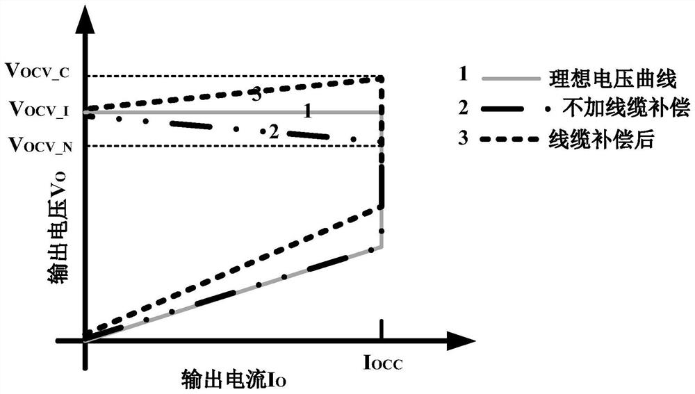
[0024] Such as figure 1 Shown is a comparison chart of the output characteristic curve of a primary-side feedback flyback converter without compensation, the output characteristic curve of the voltage compensation of the present invention, and the ideal output characteristic curve. The primary-side feedback flyback converter controlled by constant voltage output uses the error amplifier EA to amplify the error between the sampling voltage VS of the primary-side feedback flyback converter output voltage and the reference voltage VREF, and then controls the power transistor of the primary-side feedback flyback converter to conduct and off, the output characteristic voltage curve of the primary side feedback flyback converter is the ideal output characteristic voltage curve of curve 1. At this time, there is no load cable, and the output node vo...


PUM


Abstract

A voltage compensation circuit of a self-adaptive load cable comprises the following steps: firstly, converting an error amplifier output voltage containing peak current limit information of a primaryside feedback flyback converter into a first intermediate voltage related to the output current of the primary side feedback flyback converter by using an operation module; carrying out level shift conversion on the first intermediate voltage to obtain a second intermediate voltage capable of adapting to a common-mode input range of a voltage-current conversion module, and then carrying out ripple elimination conversion on the second intermediate voltage to obtain a third intermediate voltage; and enabling the third intermediate voltage to pass through a voltage-current conversion module to obtain a corresponding current, generating a voltage drop on a fifth resistor to obtain a compensation voltage in direct proportion to the output current, and superposing the compensation voltage to areference voltage for loop adjustment of the system to obtain a new reference voltage compensated by a load cable for loop adjustment of the system. Therefore, the output voltage of the primary side feedback flyback converter can change adaptively along with the load current, and the stability of the actual charging voltage is ensured.

Description

technical field [0001] The invention belongs to the technical field of analog integrated circuits, and relates to a voltage compensation circuit for an adaptive load cable, which can be applied to a primary-side feedback flyback converter controlled by constant voltage, so that the output voltage of the primary-side feedback flyback converter passes through the load The actual charging voltage provided to the load behind the cable is constant. Background technique [0002] The wide use and increasing development of portable electronic products have made the power supply industry market flourish and become larger and larger. At the same time, the market's requirements for power supply products are becoming more and more stringent. Lithium batteries can provide 3-4 times the power of lead-acid batteries of the same volume due to the amount of charge released per unit mass (ie specific capacity) as high as 3861mAh / g. In the application of portable electronic products, lithium ...

Claims


Application Information

Patent Timeline
Patent Type & Authority Applications(China)
IPC IPC(8): G05F1/56
CPCG05F1/561
Inventor 周泽坤肖志平王祖傲王卓张波
Owner UNIV OF ELECTRONICS SCI & TECH OF CHINA
Why Eureka
Try Eureka