
LED display screen lamp panel fixing structure with front maintenance anti-falling function

A technology for LED display and front maintenance, which is applied to the installation of support structures, instruments, identification devices, etc., which can solve the problems of potential safety hazards, increase in the number and workload of maintenance personnel, and falling of display lamp panels, so as to achieve no hidden danger of falling , The fixing method is safe and reliable, and the effect of ensuring safety

Inactive Publication Date: 2020-11-03
TIANJIN ALLPOSSIBLE ELECTRONCI INFORMATION TECH CO LTD
View PDF7 Cites 0 Cited by
  • Summary
  • Abstract
  • Description
  • Claims
  • Application Information

AI Technical Summary

Problems solved by technology

The problem with the installation structure of the above-mentioned LED display screen is that when the LED display screen is being maintained, scaffolding needs to be set up, and the acrylic protective plate can only be removed by multiple people moving together to remove the display screen module, which increases the number of maintenance personnel and At the same time, there are potential safety hazards when many people work at heights; in addition, when the acrylic board ages, there is a risk of the display lamp board falling

Method used


Image

  • LED display screen lamp panel fixing structure with front maintenance anti-falling function
  • LED display screen lamp panel fixing structure with front maintenance anti-falling function
  • LED display screen lamp panel fixing structure with front maintenance anti-falling function

Examples


Embodiment Construction

[0019] The present invention will be described in further detail below in conjunction with the accompanying drawings.

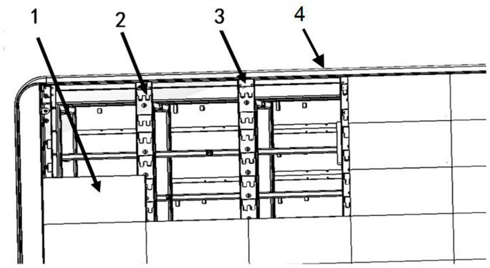
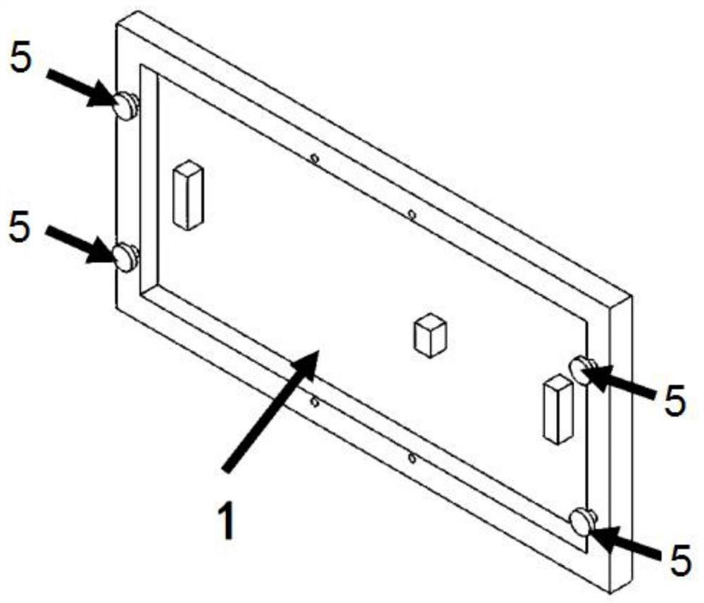
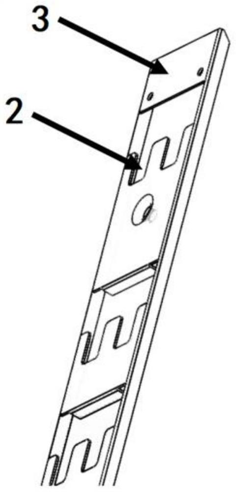
[0020] A LED display light panel fixing structure with front maintenance and anti-dropping functions, such as Figure 1 to Figure 4 As shown, it includes LED display lamp board 1, double-layer vertical bars 3 and LED main frame 4, and the double-layer vertical bars are multiple pairs, and many pairs of double-layer vertical bars are installed in parallel on the LED main frame. The vertical U-shaped fixing slots 2 are symmetrically formed on the surface of the vertical bar, and four magnet fixing parts 5 are symmetrically installed at both ends of the back of the LED display panel. In this embodiment, the magnet fixing parts are made of outer wire The specific installation method of the magnet is as follows: four threaded holes are symmetrically made on both ends of the back of the LED display panel, and an outer wire magnet is installed in each threaded hole,...


PUM


Abstract

The invention discloses an LED display screen lamp panel fixing structure with front maintenance anti-falling function. The LED display screen lamp panel fixing structure is technically characterizedby comprising a plurality of LED display screen lamp panels and an LED main frame, double-layer vertical rods are installed on the front face of the LED main frame in parallel, and U-shaped fixing clamping grooves are symmetrically formed in the surfaces of the double-layer vertical rods; four magnet fixing pieces are symmetrically installed at the two ends of the back of the LED display screen lamp panel, and each LED display screen lamp panel is installed in the U-shaped fixing clamping groove of the double-layer vertical rod through the four magnet fixing pieces and is locked and fixed. TheLED display screen lamp panel is fixed to the main frame in the mode that the magnet fixing pieces are attracted and fixed and slide downwards to be clamped into the U-shaped fixing clamping groovesto be locked through the weight of the magnet fixing pieces, vibration influences are avoided, stable installation of the LED display screen lamp panel and the main frame is guaranteed, and the LED display screen lamp panel has the advantages of being convenient and fast to install and maintain, free of falling hidden danger and the like. The LED display screen lamp panel can be widely applied torailway stations.

Description

technical field [0001] The invention belongs to the technical field of LED display screens, and relates to an LED display lamp panel, in particular to a fixing structure of an LED display lamp panel with the function of front maintenance and anti-falling off. Background technique [0002] At present, LED display screens are generally installed on railway station platforms to display relevant information about train operation, and the displayed information can be used to guide passengers to take the train. [0003] The LED display on the train platform is usually composed of several display light panels, which are attached to the main frame by magnets, and the exterior is protected by an acrylic plate. The problem with the installation structure of the above-mentioned LED display screen is that when the LED display screen is being maintained, scaffolding needs to be set up, and the acrylic protective plate can only be removed by multiple people moving together to remove the d...

Claims


Application Information

Patent Timeline
IPC IPC(8): G09F9/33H05K7/14
CPCG09F9/33H05K7/14
Inventor 张阳徐建峰王圆圆张林
Owner TIANJIN ALLPOSSIBLE ELECTRONCI INFORMATION TECH CO LTD
Learn More