Centrifugal fan

A centrifugal fan and centrifugal impeller technology, applied in mechanical equipment, machines/engines, liquid fuel engines, etc., can solve the problems of high manufacturing and replacement costs, low material utilization, low stability, etc., to achieve long service life, Small size and high stability

Inactive Publication Date: 2016-03-02
上海兰桥风机有限公司
View PDF14 Cites 0 Cited by
  • Summary
  • Abstract
  • Description
  • Claims
  • Application Information

AI Technical Summary

Problems solved by technology

Taking air conditioners as an example, most of the fans in air conditioners use ordinary DC motors, which are large in size, high in power consumption, low in energy efficiency, short in life, low in stability, and loud in noise, which undoubtedly brings disadvantages to air conditioners. influences
In addition, the fixing parts of the motor in the fan that are common in the market are mostly one-piece injection molding parts or profiles, the material utilization rate is low, and the cost of manufacturing and replacement is high

Method used


Image

  • Centrifugal fan
  • Centrifugal fan
  • Centrifugal fan

Examples


Embodiment Construction

[0025] In order to understand the above-mentioned purpose, features and advantages of the present invention more clearly, the present invention will be further described in detail below in conjunction with the accompanying drawings and specific embodiments. It should be noted that, in the case of no conflict, the embodiments of the present application and the features in the embodiments can be combined with each other.

[0026] In the following description, many specific details are set forth in order to fully understand the present invention. However, the present invention can also be implemented in other ways than described here. Therefore, the protection scope of the present invention is not limited by the specific implementation disclosed below. Example limitations.

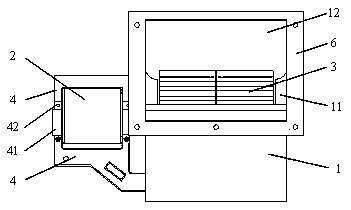
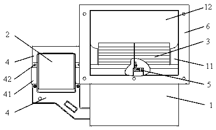
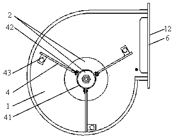
[0027] Such as Figure 1 to Figure 3 As shown, a centrifugal fan provided according to some embodiments of the present invention includes:

[0028] The volute 1, the volute 1 is a shell with an air inlet 11...


PUM


Abstract

The invention provides a centrifugal fan. The centrifugal fan comprises a volute, a motor, a centrifugal impeller and a plurality of motor supports. The volute is a shell provided with an air inlet and an air outlet. The motor is connected with the volute. The centrifugal impeller is connected with the motor and installed in the volute, the air inlet side of the centrifugal impeller is partially or completely opposite to the air inlet, and the air outlet side of the centrifugal impeller is partially or completely opposite to the air outlet. The two ends of each motor support are connected with the motor and the volute respectively. The motor is a brushless direct current motor and is smaller in size, lower in power consumption, higher in energy efficiency, longer in service life and higher in stability compared with a common direct current motor, and therefore the use performance of the centrifugal fan is improved. Each motor support is in a sheet shape, the length direction of the motor supports is parallel with the axis direction of the brushless direct current motor, and the motor supports form a certain angle to wrap the brushless direct current motor inside. The fixing mode is safe and reliable, and the manufacturing and maintaining cost is lower.

Description

technical field [0001] The invention relates to the field of ventilation equipment, and more specifically, to a centrifugal fan. Background technique [0002] In my country, fans are general-purpose equipment with a large quantity and a wide range of applications, including smoke exhaust fans, air-conditioning fans, refrigerator fans, roof fans, and so on. Taking air conditioners as an example, most of the fans in air conditioners use ordinary DC motors, which are large in size, high in power consumption, low in energy efficiency, short in life, low in stability, and loud in noise, which undoubtedly brings disadvantages to air conditioners. influences. In addition, most of the fixing parts of the motor in the fan in the market are integral injection molding parts or profiles, the material utilization rate is low, and the cost of manufacturing and replacement is high. [0003] The above-mentioned situation generally exists in the industry and has become an urgent problem to...

Claims


Application Information

Patent Timeline
IPC IPC(8): F04D25/08F04D29/00
Inventor 杨春勇
Owner 上海兰桥风机有限公司
Why Eureka
Try Eureka