
Self-energy-taking power supply device for power equipment state detection sensor

A state detection and power equipment technology, applied in battery circuit devices, electromechanical devices, circuit devices, etc., can solve problems such as limited battery power, inability to supply power to sensors, and monitoring interruptions

Inactive Publication Date: 2020-11-03
李咏琪
View PDF0 Cites 2 Cited by
  • Summary
  • Abstract
  • Description
  • Claims
  • Application Information

AI Technical Summary

Problems solved by technology

[0003] The purpose of power equipment status monitoring is to use effective detection methods and analysis and diagnosis techniques to timely and accurately grasp the equipment operating status to ensure the safe, reliable and economical operation of the equipment. The overhead cables are supported by electric poles and erected on electric vehicles. The air above the driving track is a special form of transmission line used to directly supply power to it when it is in contact with it. The existing sensor power supply device is generally powered by a battery, but the power of the battery is limited and cannot provide power for the sensor for a long time. Replacing the battery will cause interruption of monitoring

Method used


Image

  • Self-energy-taking power supply device for power equipment state detection sensor
  • Self-energy-taking power supply device for power equipment state detection sensor
  • Self-energy-taking power supply device for power equipment state detection sensor

Examples


Embodiment Construction

[0024] The following will clearly and completely describe the technical solutions in the embodiments of the present invention with reference to the accompanying drawings in the embodiments of the present invention. Obviously, the described embodiments are only some, not all, embodiments of the present invention. Based on the embodiments of the present invention, all other embodiments obtained by persons of ordinary skill in the art without making creative efforts belong to the protection scope of the present invention.

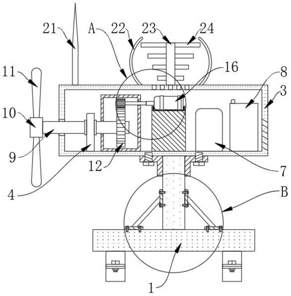
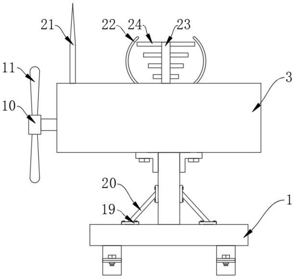
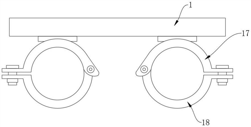
[0025] see Figure 1-5 , the present invention provides a technical solution: a self-energy-capturing power supply device for power equipment state detection sensors, including a base plate 1, the lower surface of the base plate 1 is fixedly connected with a mounting clip, and the mounting clip includes a bottom surface connected to the bottom plate 1 An upper clamp 17 is fixedly connected, and the bottom end of the upper clamp 17 is rotatably connected with a...


PUM


Abstract

The invention discloses a self-energy-taking power supply device for a power equipment state detection sensor, and the device comprises a bottom plate, wherein the upper surface of the bottom plate isfixedly connected with a supporting column, the top end of the supporting column is fixedly connected with a main body box, and the inner bottom wall of the main body box is fixedly connected with asupporting frame, a gear box, an installation seat, a charger and a storage battery. A bearing is fixedly connected to the side face of the supporting frame, and a rotating shaft is fixedly connectedto the inner ring face of the bearing. According to the self-energy-taking power supply device for the power equipment state monitoring sensor, by arranging the hinge hub and the blades, wind power can be converted into kinetic energy of rotation of the rotating shaft; by arranging the small power generator, power can be converted into electric power; by arranging the charger, electric power generated by the small power generator can be stored in the storage battery; by arranging the storage battery, the device can supply power to the sensor. Therefore, the self-energy-taking power supply device for the power equipment state monitoring sensor has the effect of integrating power generation and power storage.

Description

technical field [0001] The invention relates to the technical field of electric equipment, in particular to a self-energy-capturing power supply device used for a state detection sensor of electric equipment. Background technique [0002] A sensor is a detection device that can sense the measured information and convert the sensed information into electrical signals or other required forms of information output according to certain rules to meet the requirements of information transmission, processing, storage, display, Recording and control requirements, the characteristics of sensors include: miniaturization, digitization, intelligence, multi-function, systematization, networking, it is the first link to realize automatic detection and automatic control, the existence and development of sensors, so that objects have In addition to the senses such as touch, taste and smell, the objects slowly become alive. Usually, according to their basic perception functions, they can be ...

Claims


Application Information

Patent Timeline
IPC IPC(8): H02J7/14H02K7/18
CPCH02J7/14H02K7/1838
Inventor 陈上进
Owner 李咏琪
Learn More