Stator and permanent magnet brushless direct current motor

A stator and stator core technology, applied in the shape/style/structure of electrical components, electromechanical devices, winding conductors, etc., can solve problems such as running noise or resonance that is difficult to eliminate, large torque fluctuations, and large cogging torque , to achieve the effects of reducing cogging torque and torque ripple, increasing the slot-to-pole ratio, and increasing power density

Pending Publication Date: 2020-11-03
JIANGSU FULIHUA GENERAL EQUIP
View PDF0 Cites 0 Cited by
  • Summary
  • Abstract
  • Description
  • Claims
  • Application Information

AI Technical Summary

Problems solved by technology

Due to the structural characteristics of the permanent magnet and the stator, the cogging torque is large and the torque fluctuation is large, especially difficult to start, which may easily cause demagnetization or failure of the motor
Large torque fluctuations also cause running noise or resonance that is difficult to eliminate

Method used


Image

  • Stator and permanent magnet brushless direct current motor

Examples


Embodiment Construction

[0015] The technical solution of the present invention will be further described below in conjunction with the accompanying drawings.

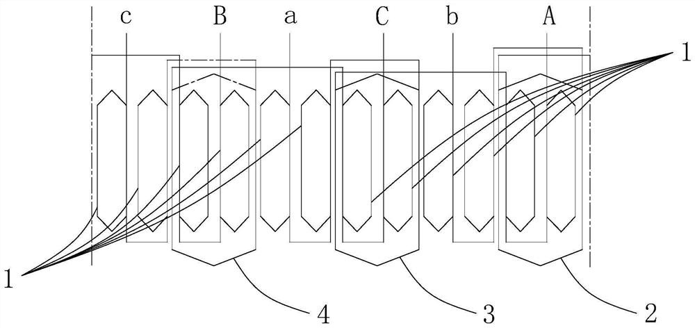
[0016] see figure 1 As shown, the above-mentioned stator includes a stator core, and the stator core is provided with at least one set of A phase, b phase, C phase, a phase, B phase, and c phase arranged in sequence, and each phase includes at least two sets of pitch. In this embodiment, each phase includes two sets of pitches.

[0017] The above-mentioned stator also includes a one-to-one corresponding element winding 1 arranged in the pitch, a B-phase auxiliary winding 2 wound on the A phase, an A-phase auxiliary winding 3 wound on the C phase, and a B-phase auxiliary winding wound on the B phase. Phase C auxiliary winding on phase 4. From figure 1 It can be seen that the B-phase auxiliary winding 2 is adjacent to the b-phase, the A-phase auxiliary winding 3 is adjacent to the a-phase, and the C-phase auxiliary winding 4 is adjacent to t...


PUM


Abstract

The invention discloses a stator, and the stator comprises a stator core; the stator core is provided with at least one group of A-phase, b-phase, C-phase, a-phase, B-phase and c-phase which are arranged in sequence; each phase comprises at least two groups of pitches; and the stator further comprises element windings arranged in the pitches in a one-to-one correspondence mode, B-phase auxiliary windings wound on the A-phase, the C-phase and the B-phase auxiliary windings; the winding direction of the B-phase auxiliary winding is opposite to that of the adjacent b-phase element winding, and the B-phase auxiliary winding is wound on all the group pitches in the A phase at the same time; the winding direction of the A-phase auxiliary winding is opposite to that of the adjacent a-phase element winding, and the A-phase auxiliary winding is wound on all the group pitches in the C phase at the same time; and the winding direction of the C-phase auxiliary winding is opposite to that of the adjacent c-phase element winding, and the C-phase auxiliary winding is wound on all the group pitches in the B phase at the same time. By arranging the auxiliary winding on the stator, the cogging torque and the torque ripple of the permanent magnet brushless direct current motor with the stator can be reduced.

Description

technical field [0001] The invention relates to a stator and permanent magnet brushless DC motor. Background technique [0002] Existing permanent magnet brushless DC motors are generally designed with three-phase symmetry and equal number of turns. Due to the structural characteristics of the permanent magnet and the stator, the cogging torque is large and the torque fluctuation is large, especially difficult to start, which may easily cause demagnetization or failure of the motor. Large torque fluctuations also cause running noise or resonance that is difficult to eliminate. Contents of the invention [0003] The purpose of the present invention is to provide a stator and a permanent magnet brushless DC motor with the stator, which can reduce the cogging torque and torque ripple of the permanent magnet brushless DC motor, and effectively improve the starting instant of the permanent magnet brushless DC motor. The excitation capacity of the stator winding in the stable ...

Claims


Application Information

Patent Timeline
Patent Type & Authority Applications(China)
IPC IPC(8): H02K3/28H02K29/03
CPCH02K3/28H02K29/03
Inventor 张唯沈坤华
Owner JIANGSU FULIHUA GENERAL EQUIP
Why Eureka
Try Eureka