An electronic expansion valve coil

An electronic expansion valve and coil technology, applied in the field of expansion valve coils and unipolar coils, can solve the problems of complex coil structure and process, disordered winding lead ends, and cumbersome parts assembly, and achieve excellent resistance to permanent deformation. Effect of surface magnetic flux density, excellent electrical insulation performance

Active Publication Date: 2018-12-04
JIANGSU LEILI MOTOR
View PDF7 Cites 1 Cited by
  • Summary
  • Abstract
  • Description
  • Claims
  • Application Information

AI Technical Summary

Problems solved by technology

[0005] 1. The utilization rate of the bobbin in the bobbin is low, and the enameled wire winding slot is only 70% full, which is a waste of space. The outer diameter of the stator assembly is 36mm, such as Figure 3B As shown, the thickness of the stator assembly is 22mm, and the volume is larger after injection molding, which wastes materials and is expensive;
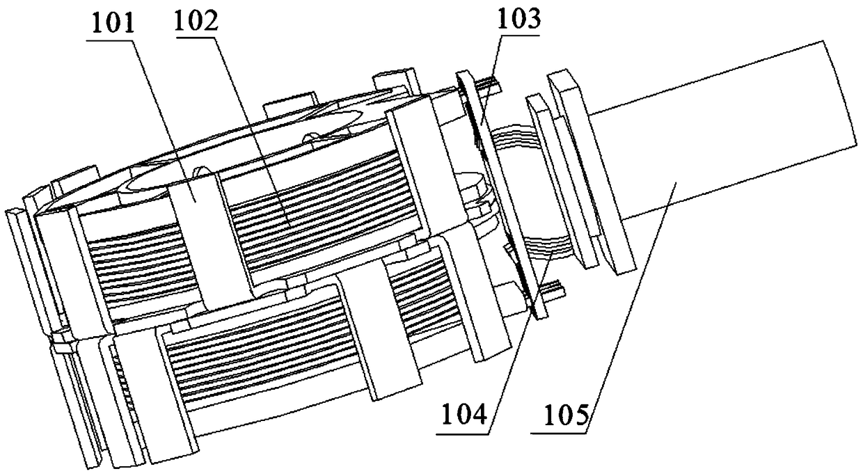
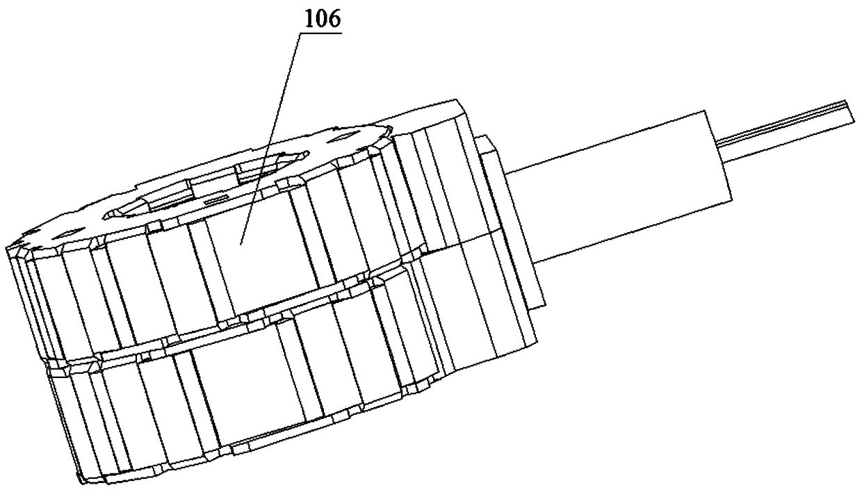
[0006] 2. The electronic expansion valve coil assembly has a complex structure and cumbersome parts assembly, such as Figure 1A and Figure 1B As shown, it is embodied in that the shell cover 106, the middle pole plate 101 and the ferrule 105 need to be assembled at the same time. During the assembly process, the shell cover 106, the middle pole plate 101 and the ferrule 105 are assembled while giving way to each other. The process It is relatively complicated and difficult to operate; tight fit is required between the middle pole plate 101 and the shell 106, and this tight fit can only be achieved by pressing with tooling;
[0007] 3. It is easy to cause motor reverse, open circuit, short circuit and other bad phenomena:
[0008] The reverse of the motor is mainly reflected in: (1) There is a line sequence when the connection line 104 and the circuit board 103 are welded, such as Figure 2A As shown, the connecting lines 104 are distinguished by six different colors, and the six separated connecting lines 104 need to be welded on different positions corresponding to the circuit board 103 respectively. Or wrong welding can easily cause the coil excitation to be reversed, thereby causing the coil assembly to be reversed; (2) In the case of correct welding of the connecting wire 104 and the circuit board 103, during the injection molding process, due to the upper and lower symmetry of the semi-finished coil device, when the electronic When the expansion valve coil assembly is placed into the mold cavity, it is easy to cause the electronic expansion valve coil assembly to be placed upside down into the mold cavity. Once it is placed upside down, the excitation of the coil assembly will be reversed, causing the coil assembly to reverse;
[0009] The open circuit and short circuit of the motor are mainly reflected in: (1) when the connecting wire 104 and the circuit board 103 are welded, the welding is reversed, and the two phases of the coil components are not connected to each other, and the circuit is broken; The electronic expansion valve coil assembly welds to form an impact, resulting in open circuit or short circuit
[0010] In order to solve the problem that the lead-out end of the connecting wire is directly exposed and affected by the flowing high-temperature and high-pressure injection molding raw materials during the injection molding process, the lead-out end of the winding will be disturbed, resulting in disordered winding energization and the reverse rotation of the motor. Patent in China, patent No.: CN03231702.6, subject name: electronic expansion valve coil, an insulating protective cover is installed on the lead-out position, to a certain extent avoid the phenomenon that the lead-out end of the connection line is crooked and broken during the injection molding process
[0011] In order to solve the problems of complex structure and process, cumbersome process, and high cost of the coil, a Chinese patent, patent number: CN201320062099.9, subject name: an electronic expansion valve coil, discloses two stators in the patent The shell, the first magnetic pole teeth are arranged inside the stator shell, and the first magnetic pole teeth are formed into a cylinder to correspond to the second magnetic pole teeth of the electromagnetic pole plate in the skeleton. Two second small holes are arranged on the stator shell, and the second small holes Fitted with the raised first small hole on the frame, this design simplifies the process to a certain extent and shortens the process flow
[0012] To sum up, in the existing disclosed technologies, there is still no effective and comprehensive solution to the above-mentioned problems of large injection molding volume, waste of materials, high cost, complex structure, cumbersome parts assembly, and easy motor reversal, circuit breaker, etc. Short circuit and other problems

Method used


Image

  • An electronic expansion valve coil
  • An electronic expansion valve coil
  • An electronic expansion valve coil

Examples


Embodiment Construction

[0044] In order to make the technical solutions of the present invention clearer and clearer to those skilled in the art, the present invention will be further described in detail below in conjunction with the examples and accompanying drawings, but the embodiments of the present invention are not limited thereto.

[0045] Such as Figure 5 , Image 6 , Figure 7 , Figure 8 with Figure 9 As shown, an electronic expansion valve coil includes a stator assembly, a circuit board 6, a connecting wire 7, and a sealant 12. The stator assembly is wrapped by a coil frame 2, an enameled wire 9 wound in the coil frame, and a middle pole plate 1. Coil bobbin 2 and casing 4 of enameled wire 9, outlet box 3, connecting post 10 connected to coil bobbin 2 and passing through outlet box 3, pole claw 11 is respectively arranged on middle pole plate 1 and casing 4, and sleeve Located outside the stator assembly, the injection molding body 5 is formed by integral injection molding of the st...


PUM


Abstract

The invention discloses a coil of an electronic expansion valve. The coil comprises a stator assembly, a circuit board, a connecting line and sealant. The stator assembly is composed of coil frameworks, a varnished wire, intermediate pole plates, a machine shell, a wire outlet box and binding posts. The intermediate pole plates and the machine shell are provided with pole pawls respectively. The coil further comprises an injection molding body arranged outside the stator assembly in a sleeving manner and formed through integral injection molding of the stator assembly. An avoiding port is formed in the part, at the wire outlet box, of the injection molding body. The binding posts are connected with the circuit board to which the connecting line is welded at the avoiding port. The sealant is arranged in a gap between the avoiding port and the circuit board. The machine shell is a cylinder with the smooth and continuous surface. The pole pawls of the intermediate pole plates and the pole pawls of the machine shell are the same in shape and size, are staggered and are opposite. The distance between the pole pawls of the intermediate pole plates and the pole pawls of the machine shell is 1.0-1.5 mm. The coil well solves the problems that the reverse direction, disconnection and short circuit of the coil of the electronic expansion valve are likely to happen.

Description

technical field [0001] The invention relates to an expansion valve coil, in particular to a unipolar coil of an electronic expansion valve, and belongs to the technical field of refrigeration control. Background technique [0002] At present, the electronic expansion valve, as a new type of control element, has become an important part of the intelligentization of the refrigeration system, and it is also an important means and guarantee for the real realization of the optimization of the refrigeration system. The opening and closing degree of the valve needle in the body part is used to control the flow of refrigerant, so as to achieve the purpose of temperature control. [0003] given in the accompanying drawings Figure 1A , Figure 1B with Figure 1C , Figure 1A , Figure 1B with Figure 1C It is a part of the manufacturing flow chart for the unipolarity of the electronic expansion valve coil in the prior art; generally, the electronic expansion valve coil assembly i...

Claims


Application Information

Patent Timeline
Patent Type & Authority Patents(China)
IPC IPC(8): F16K31/06
CPCF16K31/0675
Inventor 党红关沈文斌
Owner JIANGSU LEILI MOTOR
Why Eureka
Try Eureka