Rolled tissue rowed bagging equipment

A technology for packing bags and paper towels in a row, which is applied in the field of bagging equipment for roll paper towels in rows, and can solve the problems of slow bagging speed of roll paper

Inactive Publication Date: 2020-11-06
邹麟相
View PDF8 Cites 1 Cited by
  • Summary
  • Abstract
  • Description
  • Claims
  • Application Information

AI Technical Summary

Problems solved by technology

[0005] In order to overcome the shortcoming that it is necessary to manually hold the packaging bag to pack the roll paper, so that the speed of bagging the roll paper is slow, the technical problem to be solved is: to provide a roll paper towel that can quickly pack the roll paper into a bag. row bagging equipment

Method used


Image

  • Rolled tissue rowed bagging equipment
  • Rolled tissue rowed bagging equipment
  • Rolled tissue rowed bagging equipment

Examples


Embodiment 1

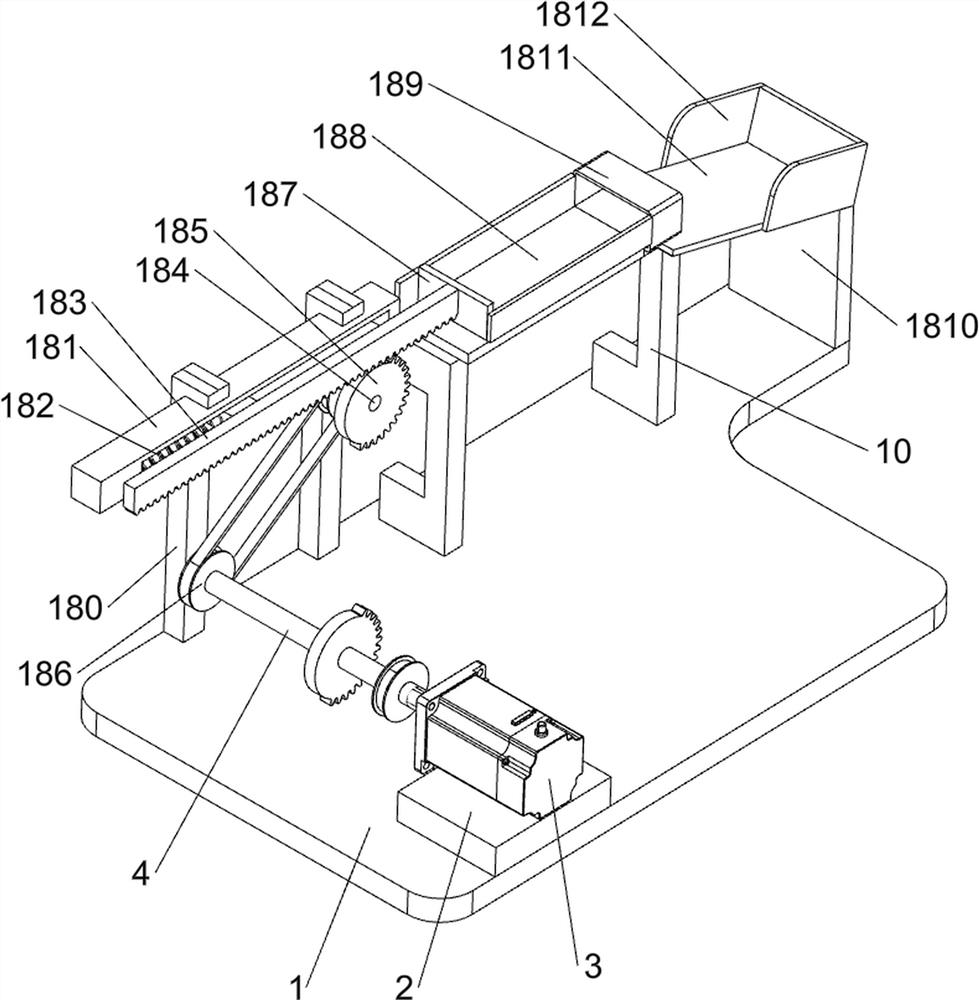
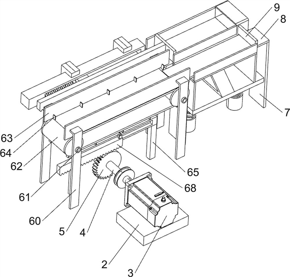
[0023] A roll-shaped paper towel bagging equipment in rows, such as Figure 1-3 and Figure 5-6 As shown, it includes a bottom plate 1, a base 2, a servo motor 3, a first rotating shaft 4, a first missing gear 5, a feeding mechanism 6, a first support plate 7, a first connecting plate 8, a baffle plate 9, and a second slide rail 10. The second slider 11, the lifting plate 12, the mounting seat 13, the second spring 14, the second support plate 15, the second protective plate 16, the pushing mechanism 17 and the bagging mechanism 18, the upper left front side of the bottom plate 1 is provided with a base 2 , the upper part of the base 2 is provided with a servo motor 3, the output shaft of the servo motor 3 is connected with a first rotating shaft 4, the first rotating shaft 4 is provided with a first missing gear 5, and the upper left rear of the base plate 1 is provided with a feeding mechanism 6, the base plate 1 The right side of the upper part is symmetrically provided wi...

Embodiment 2

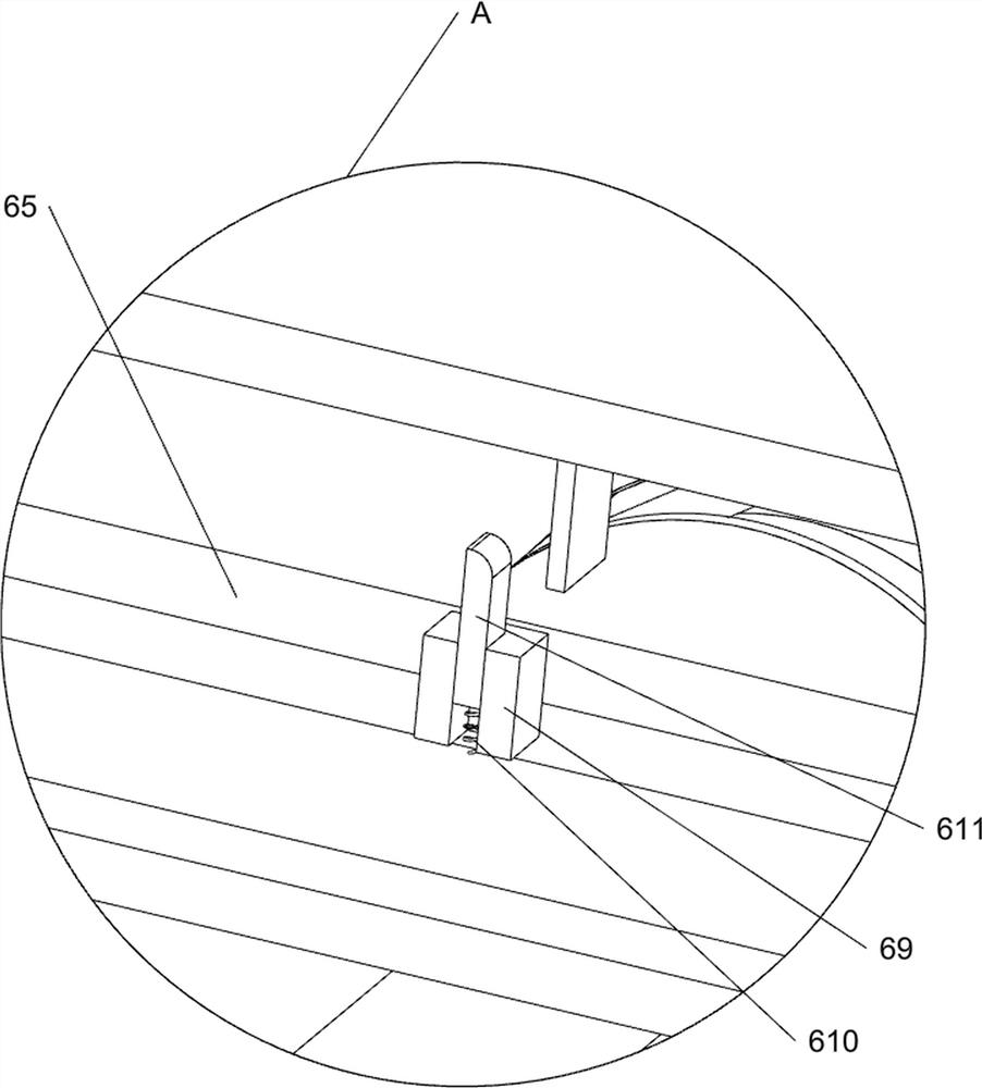
[0026] On the basis of Example 1, such as Figure 2-4 As shown, the feeding mechanism 6 includes a first bearing seat 60, a second rotating shaft 61, a conveyor belt 62, a first protective plate 63, a first push block 64, a first bracket 65, a first spring 66, a first slider 67, The first tooth bar 68, the supporting block 69, the return force spring 610 and the elevating rod 611, four first bearing seats 60 are evenly arranged on the left side of the bottom plate 1 top, and the first bearing seats 60 on the front and rear sides are all rotatably provided with The second rotating shaft 61, a conveyor belt 62 is connected between the second rotating shaft 61 on both sides, and a plurality of first push blocks 64 are arranged symmetrically front and back on the conveyor belt 62, and a first push block 64 is arranged between the first bearing blocks 60 on the left and right sides. A protective plate 63, the first protective plate 63 is positioned at the top of the conveyor belt 6...

Embodiment 3

[0033] On the basis of Example 2, such as image 3 and Figure 5 As shown, push rod 19, roller 20 and wedge block 21 are also included, push rod 172 rear portion is provided with push rod 19, push rod 19 rear end is provided with roller 20, and lifting plate 12 top is provided with wedge block 21, wedge block 21 cooperates with roller 20.

[0034] The guide block 171 moves backward to drive the push rod 19 and the roller 20 to move backward, so that the roller 20 moves along the wedge block 21, and presses the wedge block 21 downward, so that the lifting plate 12 moves downward, so that there is no need to manually move up and down Press the lifting plate 12.


PUM


Abstract

The invention relates to bagging equipment, in particular to rolled tissue rowed bagging equipment. The invention provides the rolled tissue rowed bagging equipment which comprises a bottom plate, a base, a servo motor, a first rotating shaft and a first incomplete gear. The bottom plate is used for mounting the whole equipment; the base is arranged on one side of the upper part of the bottom plate; the servo motor is arranged on the upper part of the base; the first rotating shaft is arranged on an output shaft of the servo motor; and the first incomplete gear is arranged on the first rotating shaft. The equipment achieves an effect of bagging rolled tissue quickly. By placing the paper needed to be bagged on a conveyor belt, the conveyor belt moves to a first connecting plate, and as a push plate moves front and back to push the rolled tissue to a fourth supporting plate continuously, so that a continuous bagging effect is achieved.

Description

technical field [0001] The invention relates to a bagging device, in particular to a bagging device for rolling paper towels in rows. Background technique [0002] Roll paper is a kind of household paper that is often used in modern life. Its basic composition generally includes a paper core and a paper coil wound around the periphery of the paper core. The production of web paper mainly uses wood as raw material. The wood is crushed and boiled into wood pulp, and then wood pulp is mixed with water and minerals to make pulp. After the pulp is rolled by a paper machine to remove water, the surface is ironed with a roller Flatten the large roll paper, rewind the large roll paper into small roll paper, and then cut it to become the roll paper we usually use. [0003] In order to facilitate transportation and sanitation, the roll paper will be bagged after the roll paper is produced. The traditional way of bagging the roll paper is generally by the worker holding the bag on the...

Claims


Application Information

Patent Timeline
Patent Type & Authority Applications(China)
IPC IPC(8): B65B35/44B65B35/40B65B5/10
CPCB65B5/106B65B35/405B65B35/44
Inventor 邹麟相
Owner 邹麟相
Why Eureka
Try Eureka