
Fan blade, fan blade impeller, fan assembly and air conditioning unit

A technology of fan blades and impellers is applied in the fields of fan blades, fan blades and impellers, fan components and air-conditioning units, and can solve problems such as affecting fan performance.

Active Publication Date: 2020-11-06
GREE ELECTRIC APPLIANCES INC
View PDF11 Cites 0 Cited by
  • Summary
  • Abstract
  • Description
  • Claims
  • Application Information

AI Technical Summary

Problems solved by technology

[0005] The embodiment of the present invention provides a fan blade, a fan blade impeller, a fan assembly, and an air-conditioning unit to solve the technical problem existing in the fan in the prior art that affects the performance of the fan due to the reinforcement ribs installed at the blade root of the fan blade

Method used


Image

  • Fan blade, fan blade impeller, fan assembly and air conditioning unit
  • Fan blade, fan blade impeller, fan assembly and air conditioning unit
  • Fan blade, fan blade impeller, fan assembly and air conditioning unit

Examples


Embodiment Construction

[0029] In order to make the object, technical solution and advantages of the present invention clearer, the present invention will be described in further detail below in conjunction with the embodiments and accompanying drawings. Here, the exemplary embodiments and descriptions of the present invention are used to explain the present invention, but not to limit the present invention.

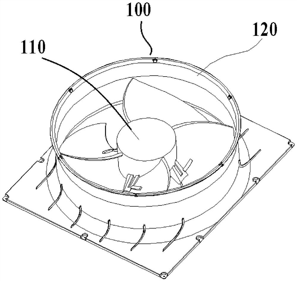
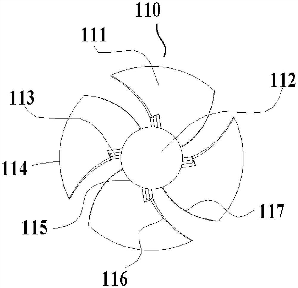
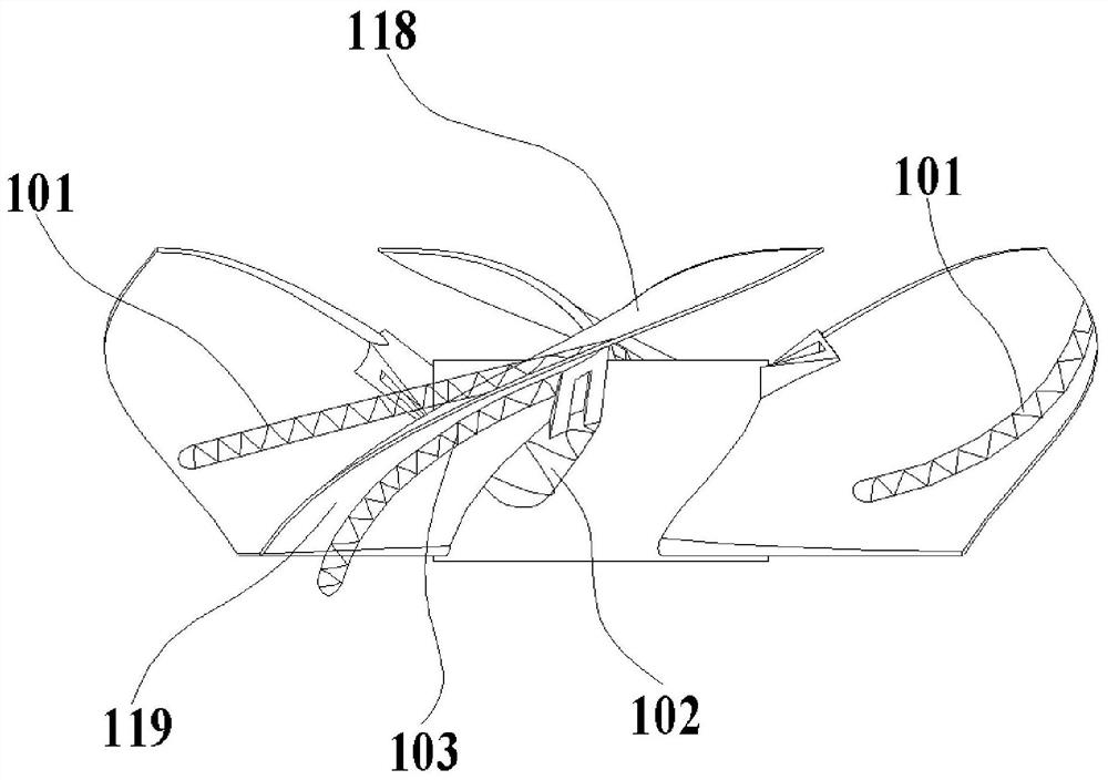
[0030] The present invention analyzes the four-blade axial flow fan in the prior art, as figure 1 As shown, the four-blade axial flow fan 100 in the prior art includes a blade impeller 110 and a guide ring 120 , and the fan blade impeller 110 is installed in the guide ring 120 . Such as figure 2 and image 3 As shown, the wind blade impeller 110 includes a blade 111, a hub 112, a rib 113, a blade top 114, a blade root 115, a leading edge 116 and a trailing edge 117, and the blade 111 is arranged on the hub 112 by its blade root 115, and the blade 111 The bottom surface is the suction surfac...


PUM


Abstract

The invention provides a fan blade, a fan blade impeller, a fan assembly and an air conditioning unit. The fan blade comprises a blade body and a reinforcing portion arranged on the blade root of theblade body. The reinforcing portion is located on the front edge of the blade body and is of a curved surface structure. Due to the fact that the reinforcing portion is located on the front edge of the blade body and is of the curved surface structure, the airflow turning angle can be reduced, airflow separation of the fan on the blade root of the blade body can be reduced, flowing losses are reduced, and the fan efficiency is improved. Thus, the problem of blade root airflow separation caused by reinforcing bars in previous impellers is avoided, energy losses are reduced, and the fan performance and efficiency are improved.

Description

technical field [0001] The invention relates to the technical field of electric fans, in particular to a fan blade, a fan blade impeller, a fan assembly and an air conditioning unit. Background technique [0002] The flow inside the impeller of axial flow fan is three-dimensional, viscous, and unsteady. When the fluid flows through the impeller, various complex vortex systems will be generated inside the impeller, which mainly include scraping vortex, channel vortex, horseshoe vortex, and tip leakage vortex. , leading edge separating vortex and trailing edge shedding vortex, etc. These vortices not only produce a huge energy loss and seriously affect the efficiency of the fan, but also are the main source of the broadband noise of the fan. Therefore, it is of great significance to study how to reduce the vortex flow inside the impeller to improve the performance of the fan. A large number of scholars at home and abroad have studied the internal flow of axial flow fans, and...

Claims


Application Information

Patent Timeline
Patent Type & Authority Applications(China)
IPC IPC(8): F04D29/38F04D29/66
CPCF04D29/388F04D29/667F04D29/666
Inventor 朱国善汤雁翔刘司轶陈帆邹先平崔剑飞
Owner GREE ELECTRIC APPLIANCES INC
Learn More