A Curved Exhaust Slit Structure at the Trailing Edge of a Turbine Blade

A turbine blade, curved technology, applied in the direction of blade support elements, machines/engines, mechanical equipment, etc., can solve the problems of large flow resistance, damage to blade structure strength, low cooling effect, etc., to improve the load resistance ability and improve Casting manufacturability, effect of reducing flow resistance and loss

Active Publication Date: 2021-12-03
DALIAN UNIV OF TECH
View PDF8 Cites 0 Cited by
  • Summary
  • Abstract
  • Description
  • Claims
  • Application Information

AI Technical Summary

Problems solved by technology

This kind of trailing edge slit cooling structure has greater flow resistance and lower cooling effect, and also has a certain damage to the structural strength of the blade

Method used


Image

  • A Curved Exhaust Slit Structure at the Trailing Edge of a Turbine Blade
  • A Curved Exhaust Slit Structure at the Trailing Edge of a Turbine Blade
  • A Curved Exhaust Slit Structure at the Trailing Edge of a Turbine Blade

Examples


Embodiment 1

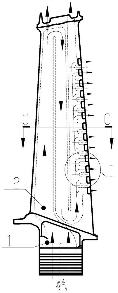
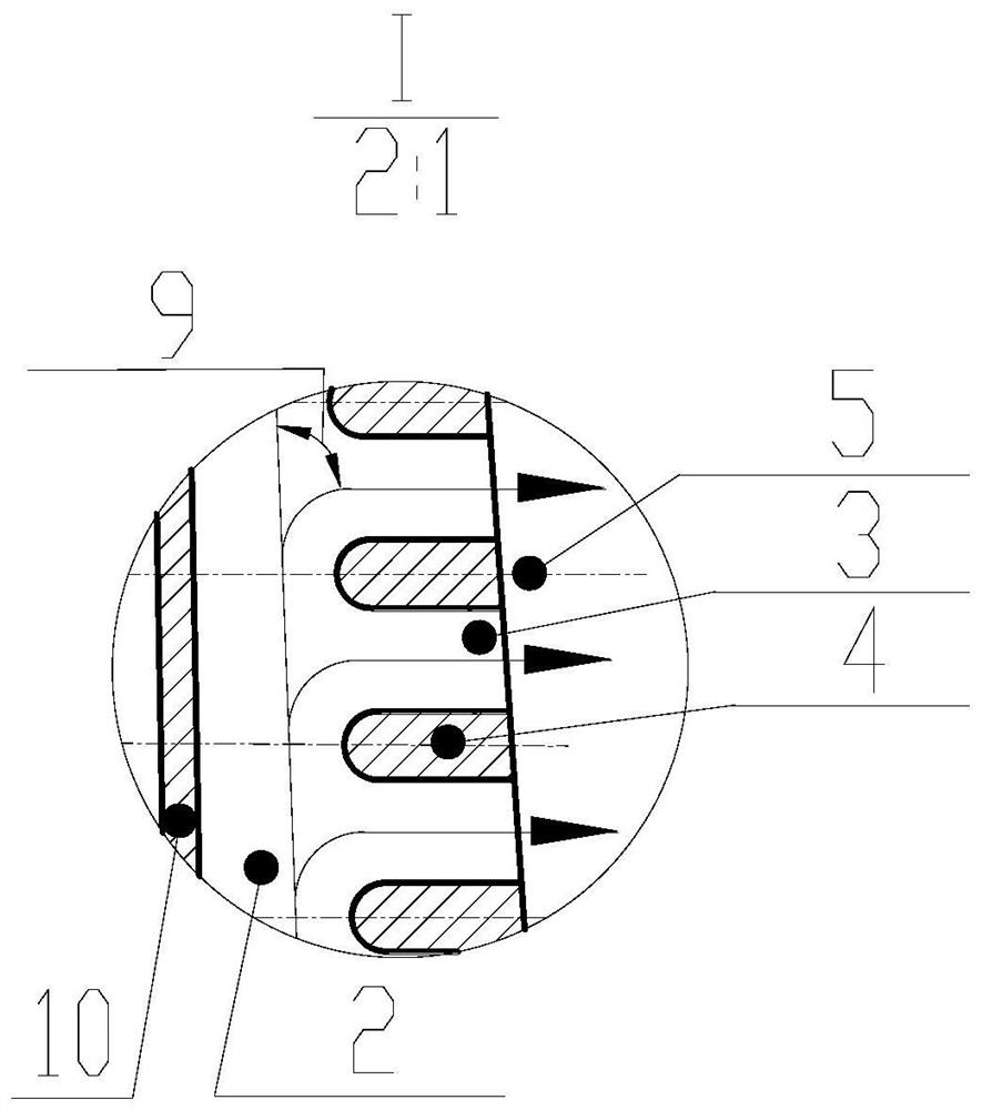
[0036] See Figure 2. A turbine blade tail ridge curve exhaust cleaning structure, including hollow turbine blades 1, inner cavity air passage 2, tail edge exhaust cleaning passage 3 and tail edge cleft ribs 4;

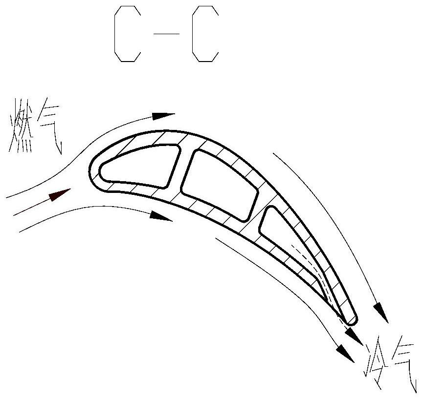
[0037] The inner chamber air passage 2 is provided inside the hollow turbine blade 1, which is lowered in the inside of the blade and cools the blades. The hollow turbine blade 1 is provided with a side-by-side tail edge cleft rib 4, and the tail rolling passage 3 is arranged in a rib 4, and the tail edge exhaust cleaning passage 3 is formed, so as to discharge the blade of the cooling gas. The leaf tail margin is covered by the gas film. The structure of the tail edge cleft rib 4 can be guided by the inside of the blade in addition to the inside of the blade, and the inner chamber cooling gas is guided so that the direction of flow occurs.

[0038] The structural shape of the tail edge cleft rib 4 is controlled by the separation rib line 5, the separation rib line 5 is a ...

Embodiment 2

[0040] See Figure 2. A turbine blade tail ridge curve exhaust cleaning structure, including hollow turbine blades 1, inner cavity air passage 2, tail edge exhaust cleaning passage 3 and tail edge cleft ribs 4;

[0041] The structural shape of the tail edge cleft rib 4 is controlled by the separating rib line 5, the separating ribs center line 5 is a circular arc or a spline, corresponding to the tail edge cleft ribs 4 form an arc shape or a spline shape. The width of the tail edge cleft ribs 4 is symmetrically distributed along the centerline of the composite rib. Tail edge exhaust cleft center line 6 is an incident angle ∠ A1 and an exit angle ∠a2 in the tangential direction and the horizontal plane angle of the air turbine blade 1 and the horizontal plane angle. Typical values ​​can be ∠A1 = 15 ° and ∠A2 = 0 °, at which time the cold air retreat is about 75 °.

Embodiment 3

[0043] See Figure 2. A turbine blade tail ridge curve exhaust cleaning structure, including hollow turbine blades 1, inner cavity air passage 2, tail edge exhaust cleaning passage 3 and tail edge cleft ribs 4;

[0044] The structural shape of the tail edge cleft rib 4 is controlled by the separating rib line 5, the separating ribs center line 5 is a circular arc or a spline, corresponding to the tail edge cleft ribs 4 form an arc shape or a spline shape. The width of the tail edge cleft ribs 4 is symmetrically distributed along the centerline of the composite rib. Tail edge exhaust cleft center line 6 is an incident angle ∠ A1 and an exit angle ∠a2 in the tangential direction and the horizontal plane angle of the air turbine blade 1 and the horizontal plane angle. Typical values ​​can be ∠A1 = 25 ° and ∠A2 = 15 °, at which time the cold air turning angle is about 65 °.


PUM


Abstract

The invention belongs to the technical field of aero-engine turbine cooling, and relates to a curved exhaust slit structure at the trailing edge of a turbine blade. The curved exhaust split structure includes a hollow turbine blade, an inner cavity cold air channel, a trailing edge exhaust split channel and a trailing edge split rib; the hollow turbine blade is provided with an inner cavity cold air channel for low temperature Cooling gas flows inside the blade to cool the blade. The trailing edge of the hollow turbine blade is provided with trailing edge split ribs arranged side by side, and a trailing edge exhaust split channel is formed between the trailing edge split ribs arranged side by side for cooling air to discharge from the blade. In the present invention, the slit of the blade trailing edge is designed as an oblique curve exhaust, which reduces the turning angle of the cooling air in the slit, so that the turning process is continuous and gentle, thereby reducing the flow resistance and loss of the cold air in the inner cavity of the blade, and can make The flow resistance is reduced by about 20%.

Description

Technical field [0001] The present invention is in the field of aviation engine turbine cooling technology, relates to a turbine blade trailing edge curve exhaust split seam construction. Background technique [0002] Increase the turbine inlet gas temperature can significantly improve the efficiency of aircraft engines and gas turbines, gas turbines but is currently before the temperature has gone far beyond the limits of the materials used can withstand, so the development of more effective turbine blade cooling technology is very urgent. For now commonly used hollow turbine blade design, and with the reinforced air convection cooling inside a heat exchanger to remove heat and to form a gas insulation film covering the discharge gas heating blade, cooling the turbine blade main problem solving means, while the required blade " larger heat transfer area inside "," air-flow resistance is smaller, "" higher heat transfer efficiency "," film-covered area greater "," less damage to ...

Claims


Application Information

Patent Timeline
Patent Type & Authority Patents(China)
IPC IPC(8): F01D5/18
CPCF01D5/186
Inventor 吕东孔星傲王晓放王楠孙一楠
Owner DALIAN UNIV OF TECH
Why Eureka
Try Eureka