Manufacturing method of tooth difference speed reducer of double-row planetary gear

A double-row planetary and reducer technology, applied in the field of high precision, can solve the problems of small reduction ratio of the reducer, low transmission accuracy, heavy weight, etc., and achieve the effect of large reduction ratio

Pending Publication Date: 2020-11-06
冯明东
View PDF0 Cites 0 Cited by
  • Summary
  • Abstract
  • Description
  • Claims
  • Application Information

AI Technical Summary

Problems solved by technology

[0003] The present invention adopts the connection method of planetary gear sets with two rows of teeth differing by one tooth or two teeth, and solves the problem of the current reducer with small reduction ratio, small transmission torque, heavy weight and large volume, easy to wear, low transmission accuracy, high manufacturing cost, and poor structure. Complicated disadvantages

Method used


Image

  • Manufacturing method of tooth difference speed reducer of double-row planetary gear
  • Manufacturing method of tooth difference speed reducer of double-row planetary gear
  • Manufacturing method of tooth difference speed reducer of double-row planetary gear

Examples


Embodiment Construction

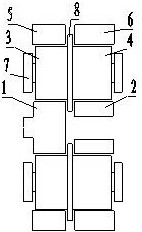
[0013] figure 1 In the shown embodiment, the front sun gear (1) inputs power, the rear sun gear (2) follows, and the front planetary gear (3) and the rear planetary gear (4) are connected and installed on the planet carrier (7) Among them, the front row ring gear (5) and the rear row ring gear (6) each fix an output power.

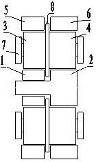
[0014] exist figure 2 In the shown embodiment, the rear row of sun gears (2) input power, the front row of sun gears (1) follow up, the front row of planetary gears (3) and the rear row of planetary gears (4) are connected and installed on the planet carrier (7) Among them, the front row ring gear (5) and the rear row ring gear (6) each fix an output power.

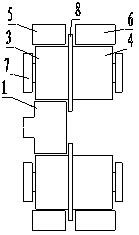
[0015] exist image 3 In the shown embodiment, there is no rear row sun gear (2), the front row sun gear (1) inputs power, and the front row planetary gear (3) is connected with the rear row planetary gear (4) and installed in the planet carrier (7) , the front row ring gear (5) and the rear row ...


PUM


Abstract

The invention discloses a manufacturing method of a tooth difference speed reducer of a double-row planetary gear, belongs to speed reducers, and particularly relates to a speed reducer which is highin precision, large in reduction ratio and easy to manufacture. The problems that a traditional speed reducer is difficult to manufacture and assemble, small in reduction ratio, small in transmissionpower, poor in precision, prone to abrasion and large in weight and size are solved. Two rows of planetary gear sets with the tooth number difference of one tooth or two teeth are adopted for connection, and the large reduction ratio is obtained through the tooth difference. The manufacturing method disclosed by the invention is mainly applied to speed reduction equipment which is small in size, light in weight, high in precision, large in transmission ratio and large in transmission force, and particularly the speed reducer needed by automatic production.

Description

technical field [0001] The present invention belongs to a speed reducer, in particular to a speed reduction device with high precision and large reduction ratio. Background technique [0002] With the continuous improvement of technology and living standards, the demand for reducers in automated production and mechanical equipment is also increasing, especially reducers with small size, simple and reliable structure, high precision, high suburban rate and large reduction ratio. At present, the existing reducers are divided into conventional cylindrical gear reducers, planetary reducers, worm reducers, harmonic reducers, and RV cycloid reducers. The cylindrical gear reducer has a large volume and a small reduction ratio. The planetary reducer is small in size and can support large torque, but the reduction ratio is small. The transmission rate of the worm reducer is low and easy to wear, and the harmonic reducer is small in size and large in transmission ratio, but it is no...

Claims


Application Information

Patent Timeline
Patent Type & Authority Applications(China)
IPC IPC(8): F16H57/023F16H55/08
CPCF16H55/08F16H57/023F16H2001/289F16H2001/327F16H2057/02017
Inventor 冯明东
Owner 冯明东
Why Eureka
Try Eureka