Control method of printer and printer thereof

A control method and a printer technology, which are applied in printing, transfer materials, and letter-spacing mechanisms, etc., and can solve problems such as fading printed characters and insufficient ink

Inactive Publication Date: 2008-07-09
STAR MICRONICS
View PDF6 Cites 0 Cited by
  • Summary
  • Abstract
  • Description
  • Claims
  • Application Information

AI Technical Summary

Problems solved by technology

However, if the ribbon is not wound, and the printing width is narrow and there are multiple continuous lines, then, because the dots of the print head...

Method used


Image

  • Control method of printer and printer thereof
  • Control method of printer and printer thereof
  • Control method of printer and printer thereof

Examples


Embodiment Construction

[0021] Hereinafter, an embodiment of the present invention will be described with reference to the drawings.

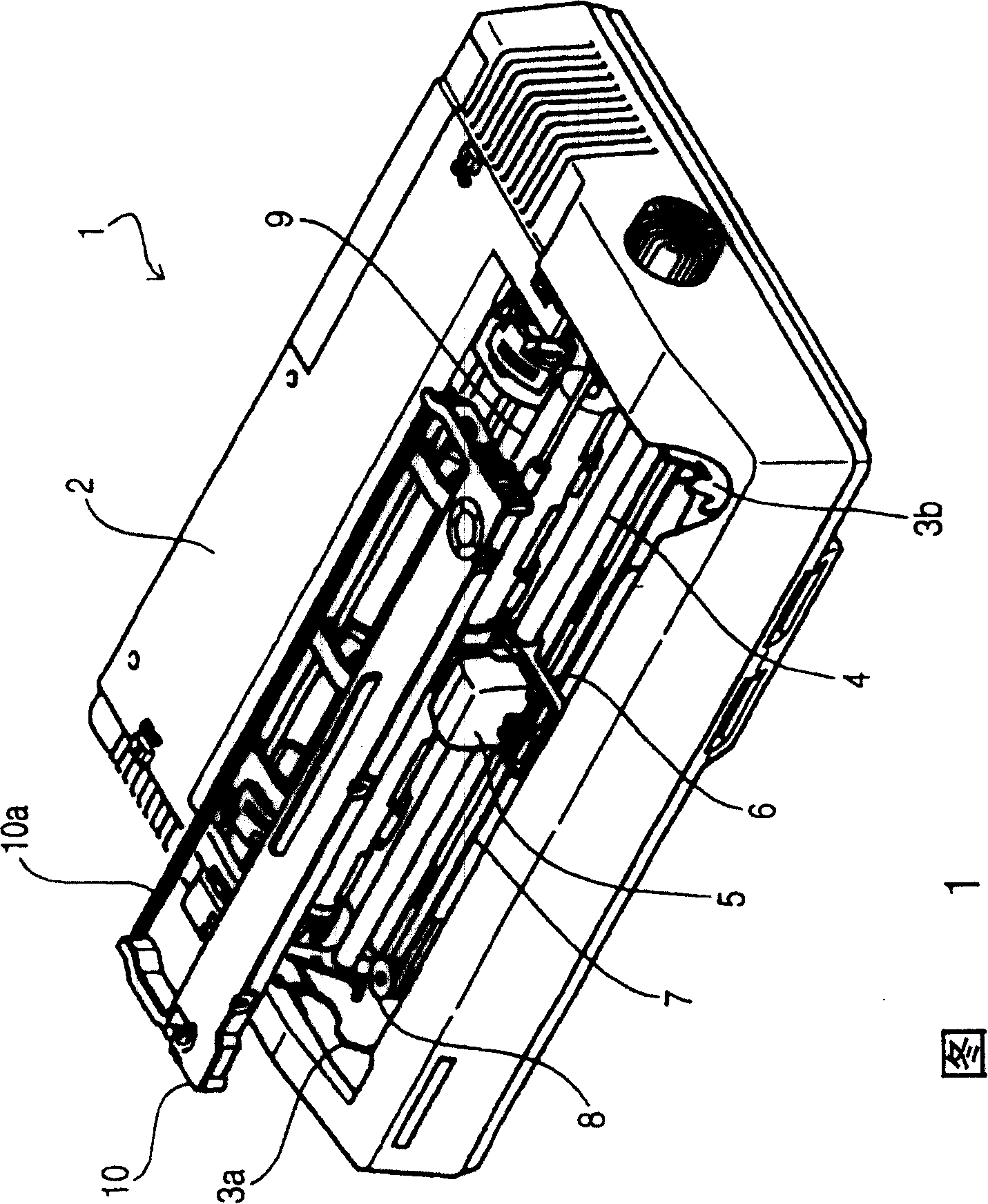
[0022] FIG. 1 shows an overall schematic diagram of a printer 1 related to this embodiment, in which reference numeral 2 denotes a casing, and 3a, 3b denote machine frames. The carriage guide 4 is supported by the machine frames 3a and 3b, and along the carriage guide 4, the carriage 6 on which the printing head 5 is mounted is supported and can freely move back and forth. The carriage 6 is fixed on a section of synchronous belt 7 arranged below it, and will also move back and forth following the back and forth movement of the synchronous belt 7 . The timing belt 7 is wound around a driven pulley 8 and a driving pulley (not shown), and the carriage 6 is driven by a carriage driving motor 41 (see FIG. 5 ) that rotates the driving pulley. The carriage drive motor 41 and the timing belt 7 are the carriage drive mechanism at this time.

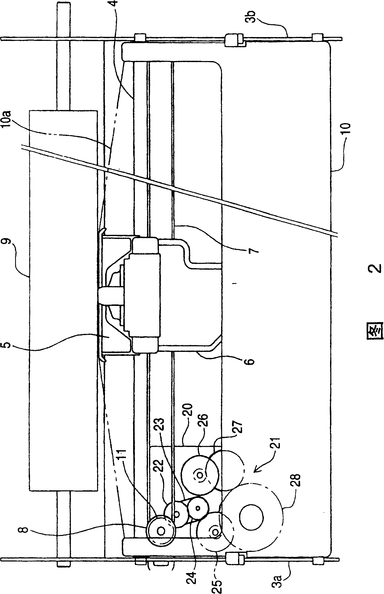
[0023] FIG. 2 is a plan view sho...


PUM


Abstract

The invention provides a method for controlling a printer and, a printer wherein a movement amount of a carriage is shortened as much as possible for shortening a printing time, and at the same time, an ink ribbon is surely taken up even when a printing region of one line is short. From a carriage movement start position to an ink ribbon take-up start position where speed reducing gears 21 drive thereby actually taking up the ink ribbon 10a is set as an ink ribbon non take-up region. Before the carriage 6 starts moving, it is judged whether or not the movement amount of the carriage 6 required for printing one line exceeds the ink ribbon non take-up region. When the movement amount does not exceed the region, a slow down region of the carriage 6 is increased until the movement amount exceeds the ink ribbon non take-up region.

Description

technical field [0001] The invention relates to a printing type printer with a ribbon, especially the winding control technology of the ribbon. Background technique [0002] The printing head installed on the carriage of this kind of printer makes dots on the printing paper sandwiched between the paper roll and the ribbon rolled out from the ribbon cassette in the form of multiple dots, recording dot matrix printing graphics. The print head moves back and forth along the color ribbon by the carriage, and the back and forth movement prints a line and feeds a line of paper alternately and repeatedly. In this type of printer, usually, the winding of the ribbon is linked to the movement of the carriage. For this purpose, for example, a timing belt for moving the carriage and a ribbon winding shaft of the ribbon cassette are coupled by a reduction gear set. At this time, in the reduction gear set, regardless of whether the carriage is coming or going, a switching means such as ...

Claims


Application Information

Patent Timeline
IPC IPC(8): B41J33/14B41J23/02B41J19/18B41J19/20B41J31/00B41J33/22B41J33/388B41J33/54
Inventor 望月宏
Owner STAR MICRONICS
Why Eureka
Try Eureka