Novel electric safety locking device

A safety lock, electric technology, applied in the direction of electric locks, electric car locks, building locks, etc., can solve the problems that the locking action is not in place, can not apply to non-compressed air source, does not have reverse self-locking, etc., to achieve locking maintain reliable performance

Active Publication Date: 2021-06-22
NANJING INST OF TECH
View PDF7 Cites 2 Cited by
  • Summary
  • Abstract
  • Description
  • Claims
  • Application Information

AI Technical Summary

Problems solved by technology

Most of the existing safety locking devices are pneumatic safety locks with compressed air as the power source, which cannot be applied to occasions without compressed air source
There are three problems in the existing electric drive safety locking device. First, the insufficient output driving torque often causes the locking action to fail to reach the designated position.
The second is that the locking action process does not have the no-load travel fast-forward function, so the locking action efficiency is not high
The third is that the actuator does not have the reverse self-locking function, so the energy consumption of the locking and holding function is large, and the reliability and safety are not high.

Method used


Image

  • Novel electric safety locking device
  • Novel electric safety locking device
  • Novel electric safety locking device

Examples


Embodiment Construction

[0034] The present invention will be further described below in conjunction with the accompanying drawings and specific preferred embodiments.

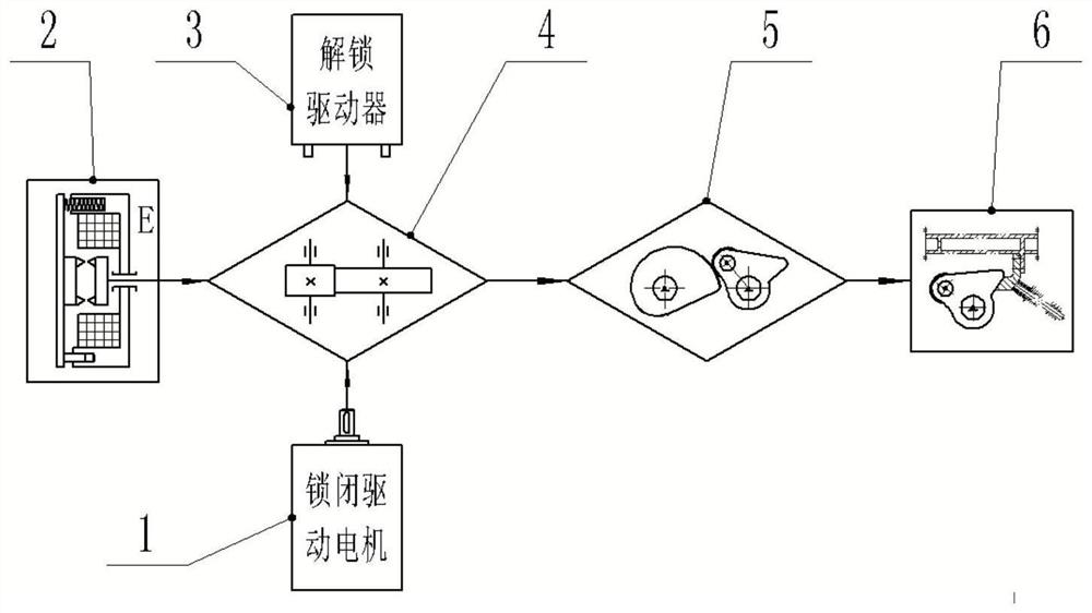
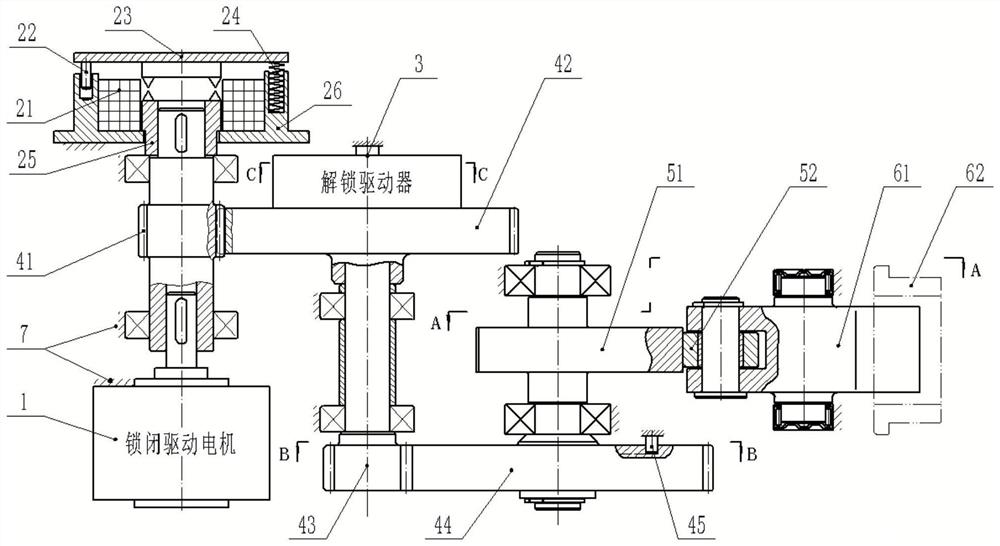
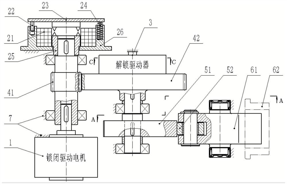
[0035] The first specific example is figure 1 and figure 2 As shown, a new electric safety locking device includes a locking drive motor 1, a locking brake 2, an unlocking driver 3, a fixed speed ratio transmission mechanism 4, a variable speed ratio actuator 5 and an actuator 6;

[0036] like figure 2 As shown, the constant speed ratio transmission mechanism 4 includes a high-speed pinion 41, a high-speed bull gear 42, a low-speed pinion 43 and a low-speed bull gear 44; 61 and its locking operation object lock 62;

[0037]The high-speed pinion 41 is fixedly nested on the output shaft of the locking drive motor 1, the high-speed pinion 41 is engaged with the high-speed bull gear 42 for transmission, and the high-speed bull gear 42 and the low-speed pinion 43 are coaxial Rotate, the low-speed pinion gear 43 and the low-speed bull...


PUM


Abstract

The invention relates to a novel electric safety locking device. The locking device comprises a locking driving motor, a locking brake, an unlocking driver, a constant-speed-ratio transmission mechanism, a variable-speed-ratio executing mechanism and an executing component; the variable-speed-ratio executing mechanism comprises a variable-speed driving disc; the executing component comprises a spring bolt and an operation object lock catch of the spring bolt; an output shaft of the locking driving motor drives the variable-speed driving disc to rotate through the constant-speed-ratio transmission mechanism, and the variable-speed driving disc is used for driving the spring bolt to swing, so that the end of the spring bolt can press the lock catch; the locking brake can apply or release braking to the output shaft of the locking driving motor, the unlocking driver is compressed in the process that the spring bolt swings towards the lock catch direction to store energy for the unlocking action, and when the locking driving motor is powered off and the locking brake releases braking, the unlocking driver drives the variable-speed driving disc to move in the direction opposite to the locking action to realize unlocking. The locking device has the functions of locking driving, locking keeping and quick unlocking.

Description

technical field [0001] The invention relates to the application of mechanism and mechanical transmission technology in the field of door locks, specifically a new electric safety locking device. Background technique [0002] In order to ensure the safety of high-speed rail vehicle door system operation, compartment sealing and ride comfort, it is effective to add a safety locking device to the rail vehicle door system. Most of the existing safety locking devices are pneumatic safety locks with compressed air as the power source, which cannot be applied to occasions without compressed air source. There are three problems in the existing electrically driven safety locking device. One is that the insufficient output driving torque often occurs that the locking action is not in place. The second is that the locking action process does not possess the fast-forward function of the no-load stroke, so the locking action efficiency is not high. The third is that the actuator does n...

Claims


Application Information

Patent Timeline
Patent Type & Authority Applications(China)
IPC IPC(8): E05B81/06E05B81/16E05B81/34E05B83/36E05B85/00E05B85/24
CPCE05B81/06E05B81/16E05B81/34E05B83/363E05B85/24E05B85/00
Inventor 张杰史金飞高海涛荀超孙小肖王浩宇孙芮
Owner NANJING INST OF TECH
Why Eureka
Try Eureka