
Rotating shaft dynamic sealing structure and method for replacing sealing ring of rotating shaft dynamic seal

A dynamic sealing structure and sealing ring technology, applied in the direction of engine sealing, engine components, mechanical equipment, etc., can solve the problems of increased friction, easy sealing failure, etc., to prolong the service life, simplify the steps of replacing the sealing ring, The effect of saving maintenance workload and maintenance time

Pending Publication Date: 2020-11-06
陕西宏达实业有限公司
View PDF0 Cites 0 Cited by
  • Summary
  • Abstract
  • Description
  • Claims
  • Application Information

AI Technical Summary

Problems solved by technology

[0003] In the solid powder mixing device, the granular powder can easily enter the sealing ring, which will dry out the lubricating grease, increase the friction force, and cause the seal to fail easily. It is often necessary to replace the sealing ring

Method used


Image

  • Rotating shaft dynamic sealing structure and method for replacing sealing ring of rotating shaft dynamic seal
  • Rotating shaft dynamic sealing structure and method for replacing sealing ring of rotating shaft dynamic seal
  • Rotating shaft dynamic sealing structure and method for replacing sealing ring of rotating shaft dynamic seal

Examples


Embodiment Construction

[0030] In order to make the above objects, features and advantages of the present invention more comprehensible, the specific implementation manners of the present invention will be described in detail below in conjunction with the accompanying drawings.

[0031] In the following description, specific details are set forth in order to provide a thorough understanding of the present invention. However, the present invention can be implemented in many other ways than those described here, and those skilled in the art can make similar extensions without departing from the connotation of the present invention. Accordingly, the present invention is not limited to the specific embodiments disclosed below.

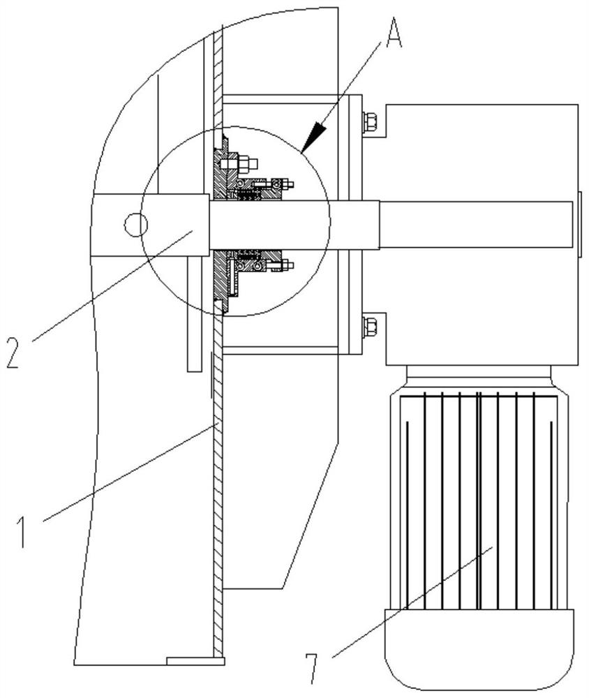
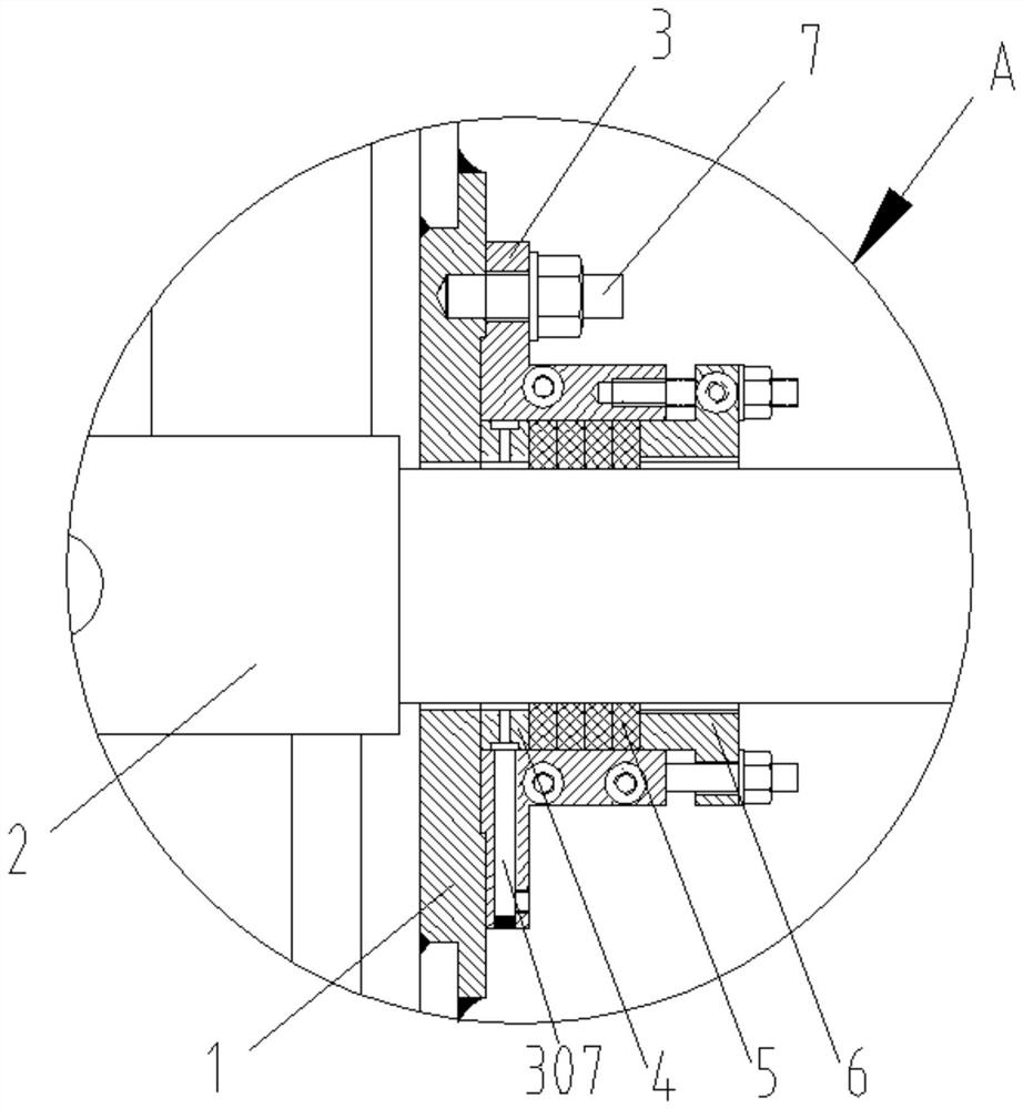
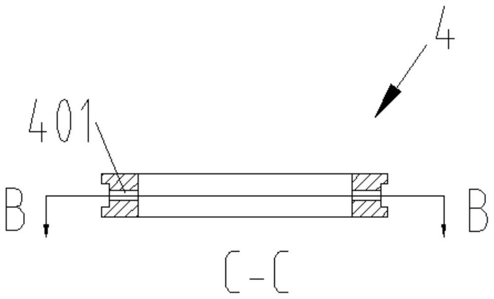
[0032] (1), please refer to figure 1 , figure 2 , image 3 with Figure 4 , a rotating shaft dynamic sealing structure, including a housing 1 and a rotating shaft 2; the housing 1 is provided with a shaft hole, the rotating shaft 2 passes through the shaft hole, and the rota...


PUM


Abstract

The invention discloses a rotating shaft dynamic sealing structure. The rotating shaft dynamic sealing structure includes a shell and a rotating shaft; a shaft hole is arranged on the shell; the rotating shaft passes through the shaft hole; the rotating shaft outside the shell is sleeved with a stuffing box; the stuffing box contains a bottom plate and a cylinder connected to one side of the bottom plate; the middle of the bottom plate is provided with a first circular hole, and the diameter of the first circular hole is larger than the diameter of the rotating shaft; a plurality of first fixing holes are arranged on the edge of the bottom plate; the stuffing box is connected to the shell by bolts; the cylinder is sequentially provided with an air blowing ring, at least two sealing rings and a stuffing box gland from the inside to the outside; the side wall of the air blowing ring is provided with an air blowing hole; the air blowing hole is connected to compressed air; and the inner diameter of the air blowing ring is larger than the diameter of the rotating shaft. The invention also discloses a method for replacing the sealing ring of the rotating shaft dynamic seal. The technical scheme reduces or avoids particle powders entering the sealing ring, and prolongs the service life of the sealing ring; and the structure of semi-stuffing boxes and semi-sealing rings simplifies thesteps of replacing the sealing ring, so that maintenance workload and maintenance time are saved.

Description

technical field [0001] The invention relates to the field of mechanical seals, in particular to a rotating shaft dynamic sealing structure and a method for replacing a sealing ring of the rotating shaft dynamic sealing. Background technique [0002] Dynamic seals are the seals between relatively moving parts in machinery and equipment. The sealing ring is often used as a component to solve the dynamic sealing between the rotating shaft and the housing. It mainly relies on the elastic force generated by the elastic sealing ring to achieve the sealing effect and prevent the medium from leaking from the high pressure end to the low pressure end. [0003] In the solid powder stirring device, the granular powder can easily enter the sealing ring, which will dry out the lubricating grease, increase the friction force, and the seal will easily fail, so the sealing ring needs to be replaced frequently. Therefore, reducing or preventing particle powder from entering the sealing rin...

Claims


Application Information

Patent Timeline
Patent Type & Authority Applications(China)
IPC IPC(8): F16J15/18
CPCF16J15/181F16J15/184
Inventor 刘凯孟宪伟李春锋
Owner 陕西宏达实业有限公司
Learn More