

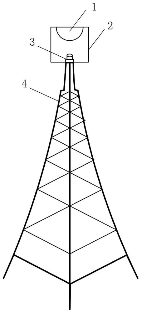
Farmland canopy temperature distribution monitoring device
A temperature distribution and monitoring device technology, applied in temperature distribution maps, measuring devices, radiation pyrometry, etc., can solve problems such as low time resolution, inability to monitor canopy temperature, inability to give full play to water saving and grain increase, etc. To achieve the effect of simple structure and strong reliability
- Summary
- Abstract
- Description
- Claims
- Application Information
AI Technical Summary
Problems solved by technology
Method used
Image

Examples
Embodiment Construction
[0020] The following will clearly and completely describe the technical solutions in the embodiments of the present invention with reference to the accompanying drawings in the embodiments of the present invention. Obviously, the described embodiments are only some, not all, embodiments of the present invention. Based on the embodiments of the present invention, all other embodiments obtained by persons of ordinary skill in the art without making creative efforts belong to the protection scope of the present invention.
[0021] The purpose of the present invention is to provide a monitoring device for the temperature distribution of the farmland canopy which can not only continuously monitor the temperature of the farmland canopy, but also take into account the field-scale coverage.
[0022] In order to make the above objects, features and advantages of the present invention more comprehensible, the present invention will be further described in detail below in conjunction with...
PUM
 Abstract
Description
Claims
Application Information