Optical lens and imaging equipment

An optical lens and lens technology, applied in optics, optical components, instruments, etc., to achieve high-quality infrared imaging, high-quality resolution capabilities, and satisfy imaging requirements

Active Publication Date: 2020-11-06
JIANGXI LIANYI OPTICS CO LTD
View PDF6 Cites 10 Cited by
  • Summary
  • Abstract
  • Description
  • Claims
  • Application Information

AI Technical Summary

Problems solved by technology

However, existing optical lenses applied to smart terminal devices cannot meet these requirements at the same time

Method used


Image

  • Optical lens and imaging equipment
  • Optical lens and imaging equipment
  • Optical lens and imaging equipment

Examples


no. 1 example

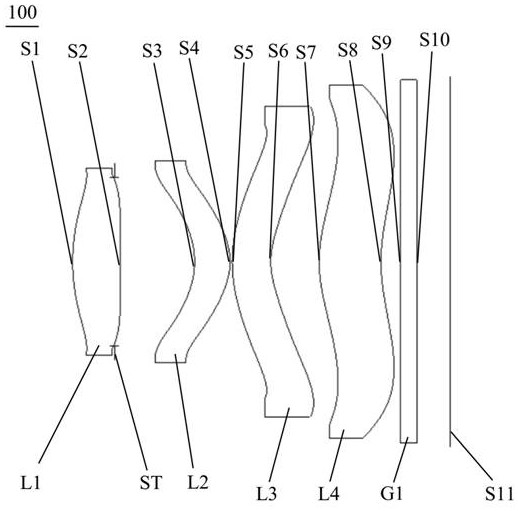
[0072] See figure 1 , A schematic view of an optical lens structure of a first embodiment of the present invention shown provided 100, the optical lens 100 along the optical axis from the object side to the imaging surface comprising in sequence: a first lens L1, aperture ST, a second lens L2, third lens L3, a fourth lens L4, and an infrared filter G1.

[0073] The first lens L1 having positive refractive power, the first lens L1 is a convex object side surface S1, a first lens L1 of the image side surface S2 is a convex surface;

[0074] The second lens L2 has a positive refractive power, a second lens L2 object side surface S3 is a concave surface, the image side surface of the second lens L2 is convex S4;

[0075] The third lens L3 has a negative refractive power, the object side surface of the third lens L3 is a convex surface S5, the third lens L3 on the image side surface S6 is a concave surface near the optical axis and the image side surface of the third lens L3 has at lea...

no. 2 example

[0090] See Figure 5 As shown in the second embodiment provides an optical lens structure diagram 200 of the present invention, the structure of the first embodiment 200 of the optical lens 100 is probably the same as in the optical lens of the present embodiment, except that: the present embodiment different materials different in optical lens 200 and the optical lens 100, and the radius of curvature of each lens.

[0091] The optical lens according to this embodiment each of the relevant parameters of the lens 200 as shown in Table 3, in the present embodiment, the image side surface of the inflection point on the optical axis S6 to the vertical distance of the third lens of the optical lens 200 is 1.865 mm, the inflection point relative to the third lens on the image side of the central arrow height is 0.566mm; inflection point on the object side surface S7 of the fourth lens to the optical axis of the vertical distance of 1.595mm, the inflection point relative to the fourth len...

no. 3 example

[0099] See Figure 9 As shown in the third embodiment provides an optical lens structure diagram 300 of the present invention, the structure of the first embodiment 300 of the optical lens 100 is probably the same as in the optical lens of the present embodiment, except that: the present embodiment different image-side surface S2 is a concave surface, and each lens is different in a first optical lens material of lens 300 and the optical lens 100, and the radius of curvature of each lens.

[0100] Table 5 shows the parameters of each lens of the optical lens 300 provided in the present embodiment, in the present embodiment, the image side surface of the inflection point on the optical axis S6 to the vertical distance of the third lens of the optical lens 300 is 1.695 mm, the inflection point relative to the third lens on the image side of the central arrow height is 0.381 mm; inflection point on the image side surface S8 to the optical axis of the vertical distance of the fourth le...


PUM


Abstract

The invention discloses an optical lens and imaging equipment. The optical lens sequentially comprises a first lens, a diaphragm, a second lens, a third lens, a fourth lens and an optical filter froman object side to an imaging surface along an optical axis, wherein the first lens has positive focal power, the object side surface of the first lens is a convex surface near the optical axis, the image side surface of the first lens is a concave surface or convex surface, the second lens has positive focal power, the object side surface of the second lens is a concave surface, the image side surface is a convex surface, the third lens has negative focal power, the object side surface of the third lens is a convex surface near the optical axis, the image side surface of the third lens is a concave surface near the optical axis, the image side surface of the third lens has at least one inflection point, the fourth lens has positive focal power, the object side surface of the fourth lens isa convex surface near the optical axis, the image side surface of the fourth lens is a concave surface near the optical axis, the image side surface of the fourth lens has at least one inflection point, and the four lenses are all plastic aspheric lenses. The optical lens provided by the invention has the characteristics of wide viewing angle, large aperture, small distortion and high-quality imaging, and is more suitable for the use requirements of the DToF technology.

Description

Technical field [0001] Technical Field The present invention relates to an imaging lens, particularly, to an optical lens and an imaging apparatus. Background technique [0002] In recent years, three-dimensional depth recognition technology has been rapid development, at the same time, with three-dimensional perception of ToF (Time of Flight, flight distance) stereoscopic camera deeply, opened a new future depth information, and by the smart terminal wide attention and application. ToF techniques can be divided according to DToF art technology and IToF ranging principle, DToF technique (direct Time-of-Flight) is a direct measurement of time of flight, DToF art technology with respect IToF with higher accuracy, shorter distance, interference strong ability advantage, relatively simple calibration. [0003] With DToF smart device technology in applications, in face recognition applications lens DToF, stereoscopic imaging, and the like in the somatosensory deepening interaction, at...

Claims


Application Information

Patent Timeline
Patent Type & Authority Applications(China)
IPC IPC(8): G02B13/18G02B13/06G02B13/14G02B1/04
CPCG02B1/041G02B13/06G02B13/14G02B13/18
Inventor 曾昊杰于笑枝刘绪明曾吉勇
Owner JIANGXI LIANYI OPTICS CO LTD
Why Eureka
Try Eureka