Optical lens and imaging device

A technology of optical lens and imaging surface, applied in optics, optical components, instruments, etc., to achieve the effect of meeting imaging requirements, good imaging requirements, and high-quality resolution capabilities

Active Publication Date: 2020-10-02
JIANGXI LIANYI OPTICS CO LTD
View PDF6 Cites 8 Cited by
  • Summary
  • Abstract
  • Description
  • Claims
  • Application Information

AI Technical Summary

Problems solved by technology

However, existing optical lenses for smartphones cannot meet these requirements at the same time

Method used


Image

  • Optical lens and imaging device
  • Optical lens and imaging device
  • Optical lens and imaging device

Examples


no. 1 example

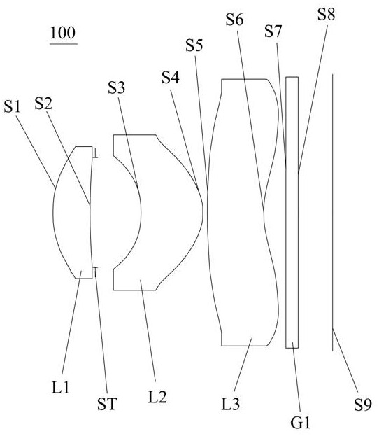
[0074] see figure 1 , which is a schematic structural view of the optical lens 100 provided by the first embodiment of the present invention, the optical lens 100 includes in sequence from the object side to the imaging surface along the optical axis: a first lens L1, a stop ST, a second lens L2, a second lens Three lens L3, and infrared filter G1.

[0075] The first lens L1 has a positive refractive power, the object side S1 is convex, and the image side S2 is concave;

[0076] The second lens L2 has a positive refractive power, its object side S3 is a concave surface, and its image side S4 is a convex surface;

[0077] The third lens L3 has negative refractive power, the object side S5 is convex, the image side S6 is concave at the near optical axis and has at least one inflection point.

[0078] The first lens L1 , the second lens L2 and the third lens L3 are all plastic aspheric lenses.

[0079] The infrared filter G1 can effectively filter out other light rays other th...

no. 2 example

[0088] see Figure 5 , which is a schematic structural view of the optical lens 200 provided in this embodiment, the structure of the optical lens 200 in this embodiment is roughly the same as that of the optical lens 100 in the first embodiment, the difference is that the optical lens in this embodiment The material of the first lens, the second lens and the third lens of the lens 200 is different from that of the optical lens 100, and the curvature radius of each lens is different.

[0089] The relevant parameters of each lens in the optical lens 200 provided in this embodiment are shown in Table 3. In this embodiment, the vertical distance from the inflection point on the image side S6 of the third lens of the optical lens 200 to the optical axis is 2.04 mm, and the sagittal height of the inflection point relative to the center of the image side of the third lens is 0.296 mm.

[0090] table 3

[0091]

[0092] The surface coefficients of each aspheric surface of the op...

no. 3 example

[0097] see Figure 9 , which is a schematic structural view of the optical lens 300 provided in this embodiment, the structure of the optical lens 300 in this embodiment is roughly the same as that of the optical lens 100 in the first embodiment, the difference is that the optical lens 300 in this embodiment The image side S2 of the first lens of the lens 300 is convex, and the materials of the first lens L1 , the second lens L2 and the third lens L3 are different from those of the optical lens 100 , and the radii of curvature of the lenses are different.

[0098] The relevant parameters of each lens in the optical lens 300 provided in this embodiment are shown in Table 5. In this embodiment, the vertical distance from the inflection point on the image side of the third lens of the optical lens 300 to the optical axis is 2.04 mm, and the sagittal height of the inflection point relative to the center of the image side of the third lens is 0.368 mm.

[0099] table 5

[0100] ...


PUM


Abstract

The invention discloses an optical lens and an imaging device. The optical lens sequentially comprises a first lens, a diaphragm, a second lens, a third lens and an optical filter from an object sideto an imaging surface along an optical axis, the first lens has positive focal power, the object side surface of the first lens is a convex surface, and the image side surface of the first lens is a concave surface or a convex surface; the second lens has positive focal power, the object side surface of the second lens is a concave surface, and the image side surface of the second lens is a convexsurface; the third lens has negative focal power, the object side surface of the third lens is a convex surface, the image side surface of the third lens is a concave surface near the optical axis, and the image side surface of the third lens has at least one inflection point; wherein the first lens, the second lens and the third lens are all plastic aspheric lenses. The optical lens provided bythe invention has the characteristics of wide viewing angle, large aperture, small distortion and high imaging quality, and is more suitable for the design requirements of the DToF technology.

Description

technical field [0001] The invention relates to the technical field of lens imaging, in particular to an optical lens and an imaging device. Background technique [0002] In recent years, 3D depth recognition technology has developed rapidly. At the same time, the ToF (Time of Flight, flight distance measurement) stereo depth-sensing lens with 3D space perception has opened up a new future of depth information and has been widely recognized in the smartphone industry. wide attention and application. ToF technology can be divided into DToF technology and IToF technology according to the principle of ranging. DToF technology (direct Time-of-Flight) is a direct measurement of flight time. Compared with IToF technology, DToF technology has higher accuracy, shorter ranging time, and anti-interference. Powerful and relatively simple to calibrate. [0003] With the launch of Apple's new iPad Pro series of tablet computers using DToF technology receiver lenses, the demand for DToF...

Claims


Application Information

Patent Timeline
Patent Type & Authority Applications(China)
IPC IPC(8): G02B13/00G02B13/06G02B13/14G02B13/18
CPCG02B13/0035G02B13/0055G02B13/008G02B13/06G02B13/14G02B13/18
Inventor 曾昊杰于笑枝刘绪明曾吉勇
Owner JIANGXI LIANYI OPTICS CO LTD
Why Eureka
Try Eureka