Optical imaging lens and imaging equipment

An optical imaging lens and lens technology, applied in the field of imaging lens, can solve problems such as inability to meet the needs of vehicle monitoring systems, poor recognition of long-distance targets, and unclear imaging of peripheral fields of view, achieving small distortion, good imaging performance, The effect of large aperture

Active Publication Date: 2021-10-08
JIANGXI LIANCHUANG ELECTRONICS CO LTD
View PDF4 Cites 0 Cited by
  • Summary
  • Abstract
  • Description
  • Claims
  • Application Information

AI Technical Summary

Problems solved by technology

[0003] However, the existing optical lenses on the market generally have disadvantages such as poor long-distance imaging and unclear peripheral field of view imaging, which leads to poor recognition of long-distance targets and cannot meet the needs of vehicle monitoring systems.

Method used


Image

  • Optical imaging lens and imaging equipment
  • Optical imaging lens and imaging equipment
  • Optical imaging lens and imaging equipment

Examples


no. 1 example

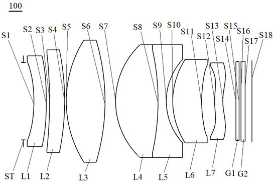
[0078] see figure 1 , which is a schematic structural diagram of the optical imaging lens 100 provided in the first embodiment of the present invention. The optical imaging lens 100 sequentially includes from the object side to the imaging surface along the optical axis: a diaphragm ST, a first lens L1, a second lens L2, the third lens L3, the fourth lens L4, the fifth lens L5, the sixth lens L6, the seventh lens L7, the filter G1, and the protective glass G2.

[0079] The first lens L1 has negative refractive power, the object side S1 of the first lens is concave, and the image side S2 of the first lens is convex;

[0080] The second lens L2 has positive refractive power, the object side S3 of the second lens is concave, and the image side S4 of the second lens is convex;

[0081] The third lens L3 has a positive refractive power, and both the object side S5 and the image side S6 of the third lens are convex;

[0082] The fourth lens L4 has positive refractive power, and bo...

no. 2 example

[0098] see Figure 5 , a schematic structural diagram of the optical imaging lens 200 provided by the second embodiment of the present invention, the optical imaging lens 200 of this embodiment is substantially the same as the above-mentioned first embodiment, the main difference is that the object side S3 of the second lens is a plane, And parameters such as curvature radius, thickness, and refractive index of each lens are different.

[0099] Specifically, the relevant parameters of each lens of the optical imaging lens 200 provided in this embodiment are shown in Table 3.

[0100] table 3

[0101]

[0102] Table 4 shows the surface shape coefficients of each aspherical surface in the optical imaging lens 200 in this embodiment.

[0103] Table 4

[0104]

[0105] The MTF diagram, vertical-axis chromatic aberration diagram, and relative illuminance diagram of the optical imaging lens 200 provided in this embodiment are respectively as follows Image 6 , Figure 7 ,...

no. 3 example

[0110] see Figure 9, a schematic structural diagram of the optical imaging lens 300 provided by the third embodiment of the present invention, the optical imaging lens 300 of this embodiment is substantially the same as the above-mentioned first embodiment, the main difference is that the object side S3 of the second lens is a convex surface, And parameters such as curvature radius, thickness, and refractive index of each lens are different. Specifically, the related parameters of each lens of the optical imaging lens 300 provided in this embodiment are shown in Table 5.

[0111] table 5

[0112]

[0113] Table 6 shows the surface shape coefficients of each aspherical surface in the optical imaging lens 300 in this embodiment.

[0114] Table 6

[0115]

[0116] The MTF diagram, vertical axis chromatic aberration diagram, and relative illuminance diagram of the optical imaging lens 300 provided in this embodiment are respectively as follows Figure 10 , Figure 11 ,...


PUM


Abstract

The invention discloses an optical imaging lens and an imaging device. The optical imaging lens comprises in sequence from the object side to the imaging surface along the optical axis: a diaphragm; a first lens with negative refractive power, the object side is a concave surface, and the image side is a concave surface. is a convex surface; the second lens with positive refractive power has a convex image side; the third lens with positive refractive power has a convex surface on both the object side and the image side; the fourth lens has positive refractive power, and its object side and The image side is convex; the fifth lens with negative refractive power, its object side and image side are concave, and the fourth lens and the fifth lens are cemented into a bonded body; the sixth lens with positive refractive power; The seventh lens with negative refractive power has a convex surface on the object side at the near optical axis, and a concave surface on the image side at the near optical axis. The optical imaging lens has the advantages of large aperture, high relative illuminance, high resolution and high imaging quality.

Description

technical field [0001] The present invention relates to the technical field of imaging lenses, in particular to an optical imaging lens and an imaging device. Background technique [0002] With the vigorous development of the automotive industry, automation and in-vehicle monitoring have begun to develop rapidly. As a key component of automatic driving assistance systems, vehicle-mounted cameras have also ushered in rapid development. Obtain all-round information inside and outside the vehicle to help drivers make correct driving behaviors. Therefore, the adaptability of the lens to the environment and imaging stability become the safety guarantee during the driving process of the car. Vehicle lenses not only need to be used in various environments such as high and low temperature conditions, acid-base corrosion conditions, but also in the case of insufficient lighting and dark light. In these occasions, the performance stability of the lens must be considered under high and...

Claims


Application Information

Patent Timeline
Patent Type & Authority Patents(China)
IPC IPC(8): G02B13/00G02B13/18G03B30/00
CPCG02B13/0045G02B13/006G02B13/18
Inventor 廖宝发魏文哲王昆王克民曾吉勇
Owner JIANGXI LIANCHUANG ELECTRONICS CO LTD
Why Eureka
Try Eureka