Random frequency hopping microwave associated imaging waveform design method

A waveform design and microwave correlation technology, which is applied in computing, radio wave measurement system, radio wave reflection/reradiation, etc., can solve the problem of unsatisfactory two-dimensional random characteristics of time and space, and achieve the goal of improving randomness and imaging performance Effect

Active Publication Date: 2017-05-24
NAT UNIV OF DEFENSE TECH
View PDF2 Cites 7 Cited by
  • Summary
  • Abstract
  • Description
  • Claims
  • Application Information

AI Technical Summary

Problems solved by technology

[0005] Aiming at the problem that the space-time two-dimensional random characteristics of the radiation field in actual microwave correlation imaging are not ideal, the present invention proposes a microwave correlation imaging waveform design method based on random frequency hopping waveforms

Method used


Image

  • Random frequency hopping microwave associated imaging waveform design method
  • Random frequency hopping microwave associated imaging waveform design method
  • Random frequency hopping microwave associated imaging waveform design method

Examples


Embodiment Construction

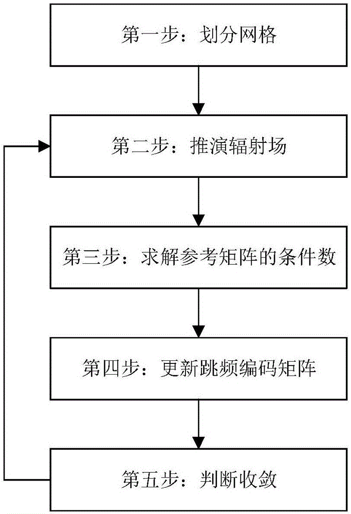
[0040] A random frequency hopping microwave correlation imaging method according to the present invention will be described in detail below in conjunction with the accompanying drawings.

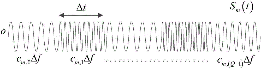
[0041] figure 2 It is a schematic diagram of the random frequency hopping signal described in the present invention. The transmission signal of each transmitting array element contains Q sub-pulses, each sub-pulse is a single-frequency signal with a length of Δt, and the signal frequency is c m,qΔf, where Δf is the minimum sub-pulse frequency interval, c m,q is the frequency hopping code. due to c m,q are randomly distributed, the transmitting waveforms of different transmitting array elements have good orthogonality, and the sub-pulses corresponding to the same transmitting array element waveforms are also irrelevant. Random frequency-hopping signals emitted by multiple transmitting array elements can form a radiation field that fluctuates randomly in time and space at the imaging plan...


PUM


Abstract

The invention provides a random frequency hopping microwave associated imaging waveform design method. According to the technical scheme, the method comprises the following steps: 1, dividing a grid, performing uniform grid division on an imaging plane, initializing iterative parameters, and generating an initial frequency hopping code matrix; 2, deducing a radiation field, calculating an iterative random frequency hopping signal each time and a reference signal corresponding to the grid center, and forming a reference signal matrix; 3, solving a condition number of the reference matrix; 4, updating a frequency hopping code matrix; and 5, ending the technical scheme if convergence is realized, otherwise returning to the second step for iterating. According to the method disclosed by the invention, the randomness of the radiation field can be continuously improved, and the aim of improving the imaging performance is finally achieved.

Description

technical field [0001] The invention belongs to the technical field of radar imaging and relates to a microwave correlation imaging waveform design method, in particular to a microwave correlation imaging waveform design method based on random frequency hopping waveforms. Background technique [0002] Microwave correlation imaging (Dongze Li, Xiang Li, Yuliang Qin, Yongqiang Cheng, and Hongqiang Wang, "Radar Coincidence Imaging: An Instantaneous Imaging Technique With Stochastic Signals," IEEE Transactions on Geoscience and Remote Sensing, vol.52, no.4, Apr. 2014) originated from optical correlation imaging, which is a new staring high-resolution imaging method that does not depend on the relative motion between the radar and the target, and can complement the traditional radar imaging system. Compared with the traditional radar imaging method that relies on the Doppler effect of the relative motion of the radar and the target to obtain high resolution, microwave correlation...

Claims


Application Information

Patent Timeline
Patent Type & Authority Applications(China)
IPC IPC(8): G01S13/89G06F17/50
CPCG01S13/89G06F30/367
Inventor 程永强王宏强周小利秦玉亮李彦鹏范波曹凯程
Owner NAT UNIV OF DEFENSE TECH
Why Eureka
Try Eureka