Source optimization method by adopting self-adaptive compressed sensing technology

A technology of compressed sensing and light source optimization, applied in optics, optomechanical equipment, micro-lithography exposure equipment, etc., can solve problems such as reduced algorithm operation efficiency, affecting the imaging performance of the lithography system, and uneven distribution of observation points

Active Publication Date: 2017-02-22
BEIJING INSTITUTE OF TECHNOLOGYGY
View PDF6 Cites 7 Cited by
  • Summary
  • Abstract
  • Description
  • Claims
  • Application Information

AI Technical Summary

Problems solved by technology

Therefore, when there are many observation points, the computational efficiency of the algorithm is significantly reduced; and when there are few observation points, the light source optimization result obtained by the algorithm will deviate from the optimal solution of the SO problem, affecting the imaging performance of the optimized lithography system
[0007] Second, the above method adopts a random sampling method when selecting observation points, so it is likely that the distribution of observation points is not uniform (that is, some areas of the circuit layout concentrate a large number of observation points, while other areas contain only a small number of observation points). Observation points, or even no observation points), at this time, some topological feature structures on the circuit layout cannot be represented by the distribution of these observation points, so it is easy to lose key information in the circuit layout structure, resulting in the obtained light source optimization results Deviation from optimal solution for SO problem
[0008] In summary, the existing SO methods need to be further improved in terms of approaching the optimal solution of the SO problem, the selection of observation points, and the efficiency of algorithm operations.

Method used


Image

  • Source optimization method by adopting self-adaptive compressed sensing technology
  • Source optimization method by adopting self-adaptive compressed sensing technology
  • Source optimization method by adopting self-adaptive compressed sensing technology

Examples


Embodiment

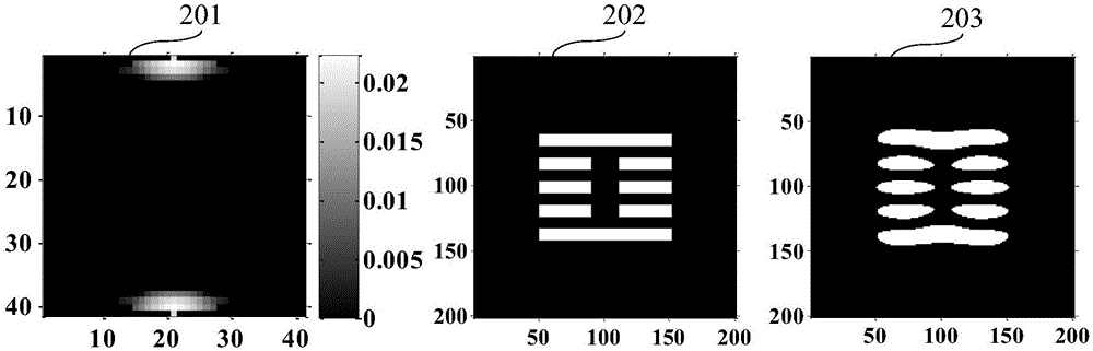
[0076] Such as figure 2Shown is a schematic diagram of the optimized light source pattern, mask pattern and its imaging in the photoresist at the best focal plane under the rated exposure amount obtained by using the traditional CS-SO method when 300 observation points are selected. 201 is an optimized light source pattern obtained by using the traditional CS-SO method, white represents the luminous area, black represents the non-luminous area, and the optimization operation time is 0.104 seconds. 202 is the mask pattern used in the simulation, which is also the target pattern, white represents the opening area, black represents the light blocking area, and its critical dimension is 45nm. Since the present invention relates to a light source optimization method, the mask pattern remains unchanged during the light source optimization process. 203 is to use 201 as the light source and 202 as the mask. When the exposure amount change and the defocus effect are not considered, t...


PUM


Abstract

The invention discloses a source optimization (SO for short) method by adopting a self-adaptive compressive sensing (CS for short) technology. Compared with an existing CS-SO algorithm, observation point distribution obtained by the SO method in the invention can better represent topological structure characteristics of a circuit layout; on the condition of a same number of observation points, computation efficiency is higher; on the condition of similar computation time of the algorithm, imaging performance of a laser lithographic system can be further improved. According to the source optimization (SO for short) method by adopting the self-adaptive compressed sensing (CS for short) technology, a blue noise sampling method is adopted to select the observation points on the circuit layout, and with a constraint condition that an imaging value at each observation point is equal to a target imaging value, a constraint condition system of linear equations is constructed. Afterwards, a self-adaptive projection matrix is constructed by using information of the circuit layout. According to the CS theory, the self-adaptive projection matrix is adopted to compress the dimensionality of the constraint condition system of linear equations, and an SO optimization question is transformed to an image restoration question of solving L-p (0<=p<=1) norm, and a CS signal is adopted to reconstruct an algorithm to optimize a source image.

Description

technical field [0001] The present invention provides a source optimization (SO) method using adaptive compressed sensing (compressive sensing, CS) technology, which belongs to the technical field of lithographic resolution enhancement. Background technique [0002] The lithography system is the core equipment used to manufacture VLSI with micron-scale and nanoscale line width. The lithography system is mainly composed of four parts: an illumination system, a mask, a projection objective lens, and a silicon wafer coated with photoresist on the upper surface. The light emitted by the light source is irradiated and passes through the mask to form a diffraction field. An image of the mask pattern is formed on the silicon wafer. [0003] For the currently commonly used 193nm ArF deep ultraviolet lithography system, as the lithography technology node enters 45-14nm, the critical dimensions of integrated circuits have entered the deep sub-wavelength range. At this time, the resol...

Claims


Application Information

Patent Timeline
Patent Type & Authority Applications(China)
IPC IPC(8): G03F7/20
CPCG03F7/70266G03F7/70275
Inventor 马旭施东向王志强李艳秋
Owner BEIJING INSTITUTE OF TECHNOLOGYGY
Why Eureka
Try Eureka