Fixed focus lens and imaging equipment

A fixed-focus lens and lens technology, applied in the field of imaging lens, can solve the problem that it is difficult to meet the diversified use requirements of drones

Active Publication Date: 2021-09-10
合肥联创光学有限公司
View PDF0 Cites 0 Cited by
  • Summary
  • Abstract
  • Description
  • Claims
  • Application Information

AI Technical Summary

Problems solved by technology

At present, conventional optical lenses on the market are difficult to meet the diversified use needs of drones

Method used


Image

  • Fixed focus lens and imaging equipment
  • Fixed focus lens and imaging equipment
  • Fixed focus lens and imaging equipment

Examples


no. 1 example

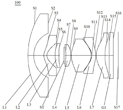
[0077] see figure 1 , is a schematic diagram of the structure of the fixed-focus lens 100 provided in the first embodiment of the present invention. The fixed-focus lens 100 includes in sequence from the object side to the imaging surface along the optical axis: a first lens L1, a second lens L2, a third lens L3, The optical centers of the diaphragm ST, the fourth lens L4, the fifth lens L5, the sixth lens L6, the seventh lens L7, and the filter G1 are located on the same straight line.

[0078] The first lens L1 has negative refractive power, the object side S1 of the first lens is a convex surface, and the image side S2 of the first lens is a concave surface;

[0079] The second lens L2 has a negative refractive power, the object side S3 of the second lens is a convex surface, and the image side S4 of the second lens is a concave surface;

[0080] The third lens L3 has positive refractive power, the object side S5 of the third lens is a convex surface, the image side S6 of ...

no. 2 example

[0096] see Figure 5 , which is a schematic diagram of the structure of a fixed-focus lens 200 provided in this embodiment, the fixed-focus lens 200 in this embodiment is roughly the same as the fixed-focus lens 100 in the first embodiment. The reason is that there are differences in the radius of curvature and thickness of each lens and the air space between each lens. Specifically, relevant parameters of each lens of the fixed-focus lens 200 in this embodiment are shown in Table 3.

[0097] table 3

[0098]

[0099] The relevant parameters of the aspheric lens of the fixed-focus lens 200 in this embodiment are shown in Table 4.

[0100] Table 4

[0101]

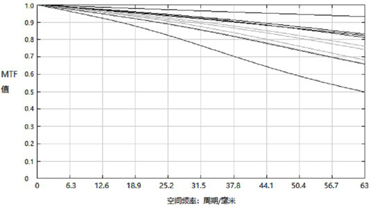
[0102] see Image 6 , shows the MTF diagram of the fixed-focus lens 200 in this embodiment. At the spatial frequency of 63 lp / mm, the MTF value of the lens within the field of view of 0.9 is above 0.6, indicating that the fixed-focus lens 200 has a higher resolution.

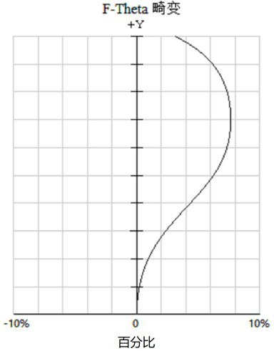
[0103] see Figure 7 , shows the F-Theta dist...

no. 3 example

[0110] see Figure 9 , shows the imaging device 300 provided by the third embodiment of the present invention, and the imaging device 300 may include an imaging element 310 and the fixed-focus lens (for example, the fixed-focus lens 100 ) in any of the above-mentioned embodiments. The imaging element 310 may be a CMOS (Complementary Metal Oxide Semiconductor, Complementary Metal Oxide Semiconductor) image sensor, and may also be a CCD (Charge Coupled Device, Charge Coupled Device) image sensor.

[0111] The imaging device 300 may be a drone, an action camera, a smart phone, a tablet computer, or any other electronic device loaded with the above-mentioned fixed-focus lens.

[0112] The imaging device 300 provided in the embodiment of the present application includes a fixed-focus lens 100. Since the fixed-focus lens 100 has the advantages of large aperture, super wide angle, miniaturization, light weight, good thermal stability, and high pixels, the imaging of the fixed-focus l...


PUM


Abstract

The invention discloses a fixed-focus lens and imaging equipment. The fixed-focus lens sequentially comprises: a first lens with negative refractive power along the optical axis from the object side to the imaging surface, the object side is convex, and the image side is concave; The second lens with negative refractive power has a convex surface on the object side and the concave surface on the image side; the third lens with positive refractive power has a convex surface on the object side and has inflection points on both the object side and the image side; the diaphragm The fourth lens with positive refractive power, its object side is concave, and the image side is convex; the fifth lens with positive refractive power, its object side and image side are convex; the sixth lens with negative refractive power, The object side is concave and the image side is convex; the seventh lens with positive refractive power has a convex object side at the near optical axis and a concave image side at the near optical axis, and the object side and image of the seventh lens are Both sides have inflection points. The fixed-focus lens has the advantages of large aperture, miniaturization, light weight, super wide angle and the like.

Description

technical field [0001] The invention relates to the technical field of imaging lenses, in particular to a fixed-focus lens and imaging equipment. Background technique [0002] With the development of mobile internet, coupled with the popularity of social networking, video, and live broadcast software, people are more and more fond of photography, and their pursuit of imaging effects is also more diversified, requiring not only high-definition image quality, but also a large field of view With the ability to capture large-scale images with strong visual impact, drones have won the favor of consumers for their unique high-altitude perspective and wide-format shooting images. At present, UAVs are developing rapidly, and correspondingly, the demand for their supporting optical lenses is also increasing. [0003] Since UAVs are often used in complex environments such as severe vibration, high pressure and extreme temperature, the performance requirements for the optical lens are...

Claims


Application Information

Patent Timeline
Patent Type & Authority Patents(China)
IPC IPC(8): G02B13/00G02B13/06G02B13/18
CPCG02B13/0045G02B13/06G02B13/18
Inventor 李伟娜高博鲍海江高航曾吉勇
Owner 合肥联创光学有限公司
Why Eureka
Try Eureka