Camera lens, camera module, electronic equipment and automobile
A camera lens and lens technology, which is applied in the direction of optical components, optics, instruments, etc., can solve the problems that it is difficult to meet the light and thin design requirements of the camera lens, and the size of the camera lens is large, so as to improve high-quality imaging images, eliminate astigmatism, and realize The effect of system miniaturization
- Summary
- Abstract
- Description
- Claims
- Application Information
AI Technical Summary
Problems solved by technology
Method used
Image
Examples
Embodiment 1
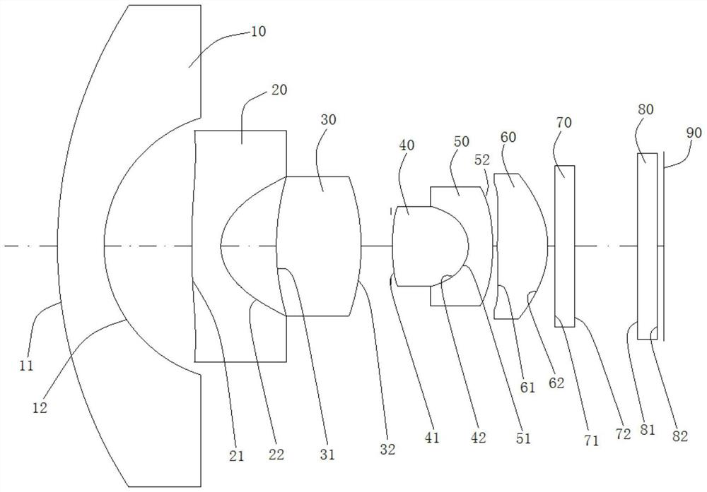
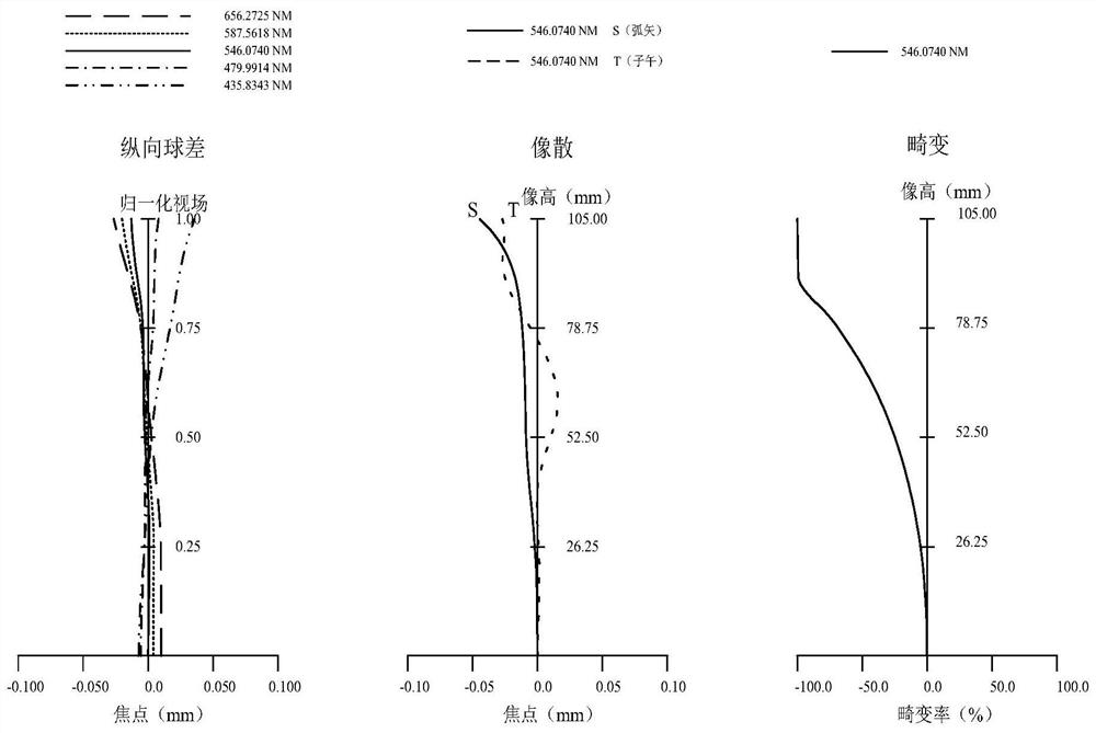
[0077] see figure 1 with figure 2 As shown, according to Embodiment 1 of the present invention, a camera lens is provided, which includes a first lens 10, a second lens, a third lens 30, a fourth lens 40, The fifth lens 50 and the sixth lens 60 .
[0078] Wherein, the first lens 10 has a negative refractive power, the object side 11 of the first lens 10 is convex at the near optical axis, and the image side 12 of the first lens 10 is concave at the near optical axis;
[0079] The second lens 20 has a negative refractive power, the object side 21 of the second lens 20 is convex at the near optical axis, and the image side 22 of the second lens 20 is concave at the near optical axis;
[0080] The third lens 30 has a positive refractive power, the object side 31 of the third lens 30 is a convex surface at the near optical axis, and the image side 32 of the third lens 30 is a convex surface at the near optical axis;
[0081] The fourth lens 40 has a positive refractive power, ...
Embodiment 2
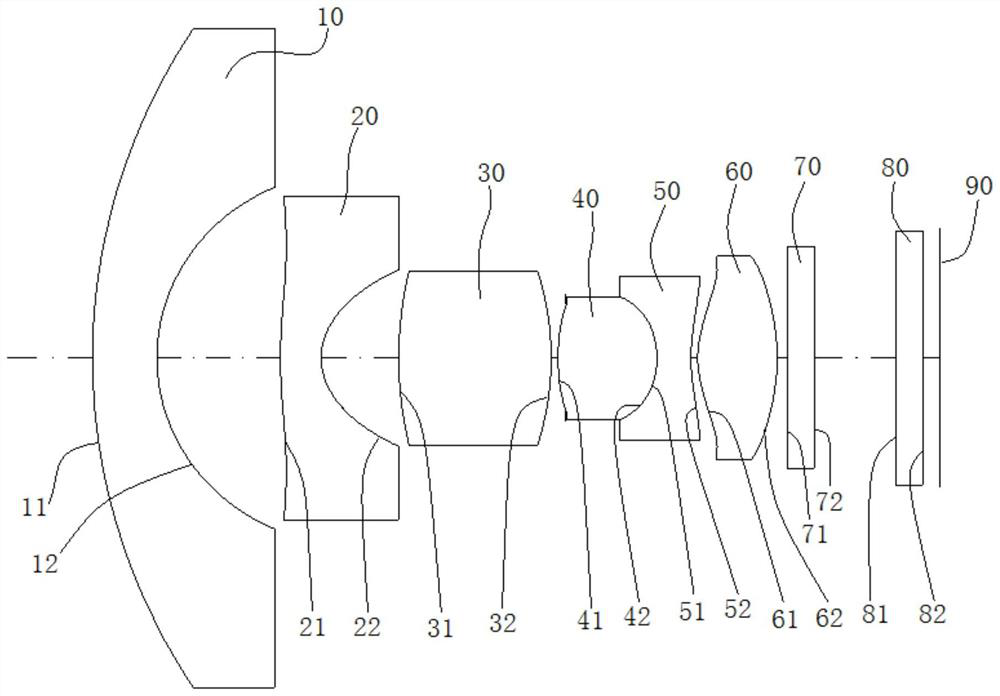
[0108] see image 3 with Figure 4 As shown, according to Embodiment 2 of the present invention, a camera lens is provided. The structure of the camera lens is basically the same as that in Embodiment 1, the difference is that the image side 52 of the fifth lens 50 in this embodiment Concave at near optical axis, not convex.
[0109] The camera lens in this embodiment satisfies the following conditional formula:
[0110] 5<(R5-R6) / (R5+R6)=7.197<10.5;
[0111] -3.2
[0112] 1.5(mm / 10 -5 / ℃)-5 / ℃)=1.601(mm / 10 -5 / ℃)-5 / °C);
[0113] 15.4
[0114] -5.5
[0115] 1.7
[0116] 11
[0117] Wherein, the above-mentioned parameters have been defined before, and will not be repeated here.
[0118] Table 3 is a characteristic table of the optical imaging lens of this embodiment, wherein each data is obtained by using visible light with a reference wavelength of 546.074nm, and the unit...
Embodiment 3
[0127] see Figure 5 with Image 6 As shown, according to Embodiment 3 of the present invention, a camera lens is provided, and the structure of the camera lens is the same as that in Embodiment 2.
[0128] The camera lens in this embodiment satisfies the following conditional formula:
[0129] 5<(R5-R6) / (R5+R6)=5.245<10.5;
[0130] -3.2
[0131] 1.5(mm / 10 -5 / ℃)-5 / ℃)-5 / °C);
[0132] 15.4
[0133] -5.5
[0134] 1.7
[0135] 11
[0136] Wherein, the above-mentioned parameters have been defined before, and will not be repeated here.
[0137] Table 5 is a characteristic table of the optical imaging lens of this embodiment, wherein each data is obtained by using visible light with a reference wavelength of 546.074nm, and the units of Y radius, thickness, and focal length are millimeters (mm).
[0138] table 5:
[0139]
[0140] Wherein, the meanings of the parameters in...
PUM
 Abstract
Description
Claims
Application Information
 - R&D
- Intellectual Property
- Life Sciences
- Materials
- Tech Scout
- Unparalleled Data Quality
- Higher Quality Content
- 60% Fewer Hallucinations
Browse by: Latest US Patents, China's latest patents, Technical Efficacy Thesaurus, Application Domain, Technology Topic, Popular Technical Reports.
© 2025 PatSnap. All rights reserved.Legal|Privacy policy|Modern Slavery Act Transparency Statement|Sitemap|About US| Contact US: help@patsnap.com


