Unmanned ship environment intelligent sensing method based on deep learning

A technology of intelligent perception and deep learning, which is applied in the field of environmental perception of unmanned ships, can solve the problems such as the inability to achieve feasible channel segmentation, and achieve the effect of taking into account real-time and accuracy

Pending Publication Date: 2020-11-06
海之韵(苏州)科技有限公司
1 Cites 0 Cited by

AI-Extracted Technical Summary

Problems solved by technology

[0003] At present, the research on target recognition technology for unmanned boats continues. For example, Chinese patent CN107609601A discloses a ship target recognition method based on multi-layer convolutional neural network. This method is only applicable to mu...

Method used

Classification decoding unit 22 processes and provides the feature map that size is 39 * 12 * 512 from encoder, obtains the bottleneck layer of 37 * 10 * 30 by it by 30 convolutional layers of 3 * 3 * 512, can greatly reduce Followed by the parameters of the fully connected layer, the environment in the ...

Abstract

The invention relates to an unmanned ship environment intelligent sensing method based on deep learning. The method comprises steps of 1, acquiring a training image data set and a test image data set;2, constructing an unmanned ship environment perception model; 3, training an unmanned ship environment perception model by using the training image data set; 4, testing the precision of the unmannedship environment perception model by using the test image data set, judging whether the unmanned ship environment perception model reaches preset precision or not, if so, executing the step 5, and otherwise, returning to the step 3; and 5, acquiring a real-time image in the sight range of the unmanned surface vehicle, and inputting the real-time image into the unmanned surface vehicle environmentsensing model to perform real-time target identification, positioning and front feasible direction segmentation on the surrounding environment of the unmanned surface vehicle. Compared with the priorart, the method is advantaged in that target recognition and feasible navigation channel segmentation are achieved at the same time, the size of the input image is not restrained, and real-time performance and accuracy are both considered.

Application Domain

Character and pattern recognitionNeural architectures +1

Technology Topic

Sight lineUnmanned surface vehicle +6

Image

  • Unmanned ship environment intelligent sensing method based on deep learning
  • Unmanned ship environment intelligent sensing method based on deep learning

Examples

  • Experimental program(1)

Example Embodiment

[0039] The technical solutions in the embodiments of the present invention will be clearly and completely described below with reference to the accompanying drawings in the embodiments of the present invention. Obviously, the described embodiments are part of the embodiments of the present invention, but not all of the embodiments. Based on the embodiments of the present invention, all other embodiments obtained by those of ordinary skill in the art without creative work shall fall within the protection scope of the present invention.
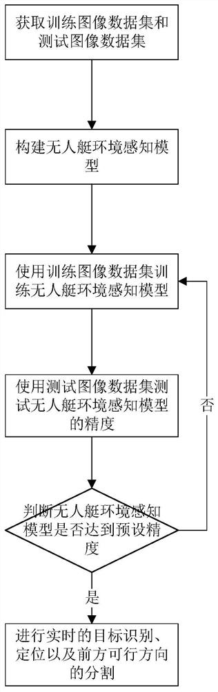
[0040] A deep learning-based intelligent perception method of unmanned boat environment, the process is as follows figure 1 shown, including:
[0041] Step 1: Obtain a training image dataset and a test image dataset;
[0042] Step 2: Build the environment perception model of the unmanned boat;
[0043] Step 3: Use the training image dataset to train the environment perception model of the unmanned boat;
[0044] Step 4: use the test image data set to test the accuracy of the unmanned boat environment perception model, and determine whether the unmanned boat environment perception model has reached the preset accuracy, if so, go to step 5, otherwise, return to step 3;
[0045] Step 5: Acquire real-time images within the sight range of the unmanned boat, and input the unmanned boat environment perception model to perform real-time target recognition, positioning and segmentation of the feasible directions ahead for the surrounding environment of the unmanned boat.
[0046] The unmanned boat environment perception model in this embodiment includes an encoder structure 1 and a decoder structure 2, the encoder structure 1 and the decoder structure 2 are connected, and the input signal of the encoder structure 1 is the training image in the training image data set, the test image Test images from image datasets or live images within sight of the drone.
[0047] The encoder structure 1 is specifically a deep convolutional neural network, and the encoder structure 1 includes a first convolutional layer 101, a first pooling layer 102, a second pooling layer 103, a third pooling layer 104, a fourth The pooling layer 105 and the fifth pooling layer 106, the first pooling layer 102, the second pooling layer 103, the third pooling layer 104, the fourth pooling layer 105 and the fifth pooling layer 106 are all 2× 2 pooling layers.
[0048]The decoder structure 2 includes a detection and decoding unit 21, a classification and decoding unit 22 and a segmentation and decoding unit 23, and the input signal of the detection and decoding unit 21 includes the output signal of the fourth pooling layer 105 and the output signal of the fifth pooling layer 106; classification and decoding The input signal of the unit 22 is the output signal of the fifth pooling layer 106 ; the input signal of the segmentation decoding unit 23 includes the signal obtained by the up-sampling of the output signal of the third pooling layer 104 and the output signal of the fourth pooling layer 105 The signal obtained after up-sampling and the output signal of the fifth pooling layer 106 .
[0049] The unmanned boat environment perception model is provided with a ROI-align layer 3, and the encoder structure 1 is connected to the detection and decoding unit 21 through the ROI-align layer 3.
[0050] The detection and decoding unit 21 includes a second convolution layer 211, a splicing module 212, a first convolution kernel 213 and a second convolution kernel 214. The input end of the second convolution layer 211 is connected to the output end of the fifth pooling layer 106, The output end of the second convolution layer 211 is connected to the input end of the splicing module 212 and the input end of the first convolution kernel 213 respectively. The output end of the first convolution kernel 213 is connected to the input end of the splicing module 212. The splicing module 212 The input end of the ROI-align layer is also connected to the output end of the ROI-align layer 3, the output end of the splicing module 212 is connected to the second convolution kernel 214, and the output signal of the second convolution kernel 214 is the prediction result data of the target bounding box. The first convolution kernel 213 and the second convolution kernel 214 in this embodiment are both 1*1 convolution kernels.
[0051] The segmentation and decoding unit 23 includes a fourth convolution layer 231, a first deconvolution layer 232, a fifth convolution layer 233, a second deconvolution layer 234, a sixth convolution layer 235, and a third deconvolution layer that are connected in sequence Layer 236, the input of the fourth convolution layer 231 is connected to the fifth pooling layer 106, and the input signal of the fifth convolution layer 233 includes the output signal of the first deconvolution layer 232 and the output of the fourth pooling layer 105 The signal after the signal is up-sampled, the input signal of the sixth convolution layer 235 includes the output signal of the second deconvolution layer 234 and the output signal of the third pooling layer 104 after the up-sampling process.
[0052] Step 5 in this embodiment is specifically:
[0053] The camera installed on the unmanned boat is used to obtain the real-time image realized in front of the sailing, and the image is input into the trained unmanned boat environment perception model, and the recognition is carried out every 10 frames, and the recognition results and positioning of the objects in the realization and the front are obtained in real time. The segmentation of feasible channels, and the identification results can also be used in subsequent path planning algorithms.
[0054] The above structure is further described below:
[0055] First, an image with a size of 1248×384×3 is input. The first convolutional layer 101 of the encoder adopts a 3×3 convolution kernel, padding=1, and then passes through five 2×2 pooling layers, that is, the first pooling Layer 102 to the fifth pooling layer 106 to obtain feature maps with sizes of 624×192×64, 312×96×128, 156×48×128, 78×24×256 and 39×12×512, respectively, where the size is The feature map of 39×12×512 is provided to the three decoder units at the same time; the feature map of size 78×24×256 is matched with the initial prediction of the detection decoder unit 21 for ROI-align and is provided to the detection and decoding unit 21 for incremental prediction ; The feature maps of size 78×24×256 and 156×48×128 have not yet been segmented. The decoding unit 23 uses the FCN-8s method to provide two-layer feature maps.
[0056] The classification and decoding unit 22 processes the feature map with a size of 39 × 12 × 512 provided by the encoder, and passes it through 30 convolutional layers of 3 × 3 × 512 to obtain a bottleneck layer of 37 × 10 × 30, which can greatly reduce the number of subsequent connections. The parameters of the connection layer are used to classify the environment in the field of view through the fully connected layer. They are divided into two categories: wide-area environment and non-wide-area environment. Obtaining a classification prediction of 1×2 is the probability of being predicted as these two categories, respectively. The larger one is the classification output signal.
[0057] The detection and decoding unit 21 processes the feature map of size 39 × 12 × 512 from the encoder, passes it through 500 convolutional layers of 1 × 1 × 512, and obtains a tensor of 39 × 12 × 500, and then passes it through 1 × The convolution kernel of 1 obtains an initial prediction of 39×12×6, in which the first two channels form a rough segmentation of the image, representing confidence, and the last four channels represent the prediction of the coordinates of the bounding box centered on the unit, thereby obtaining the boundary The initial prediction of the box, and then return the initial prediction to the feature map of size 78 × 24 × 256 generated by the encoder structure 1, that is, on the output signal of the fourth pooling layer 105, according to the ROI proposed in Mask R-CNN The -align method proposes the ROI region, and combines the corresponding feature map with the 39×12×500 tensor that generated the initial prediction to generate incremental predictions, which are added as offsets to the initial predictions to get the final prediction results.
[0058] The segmentation decoding unit 23 first processes the feature map of size 39 × 12 × 512 generated by the encoder and passes it through two convolutional layers of 1 × 1 × 512 to obtain a scale1 of size 39 × 12 × 2, two channels are the distribution of pixels in the drivable area and the non-driving area, respectively. A deconvolution of scale1 of size 39×12×2 is performed to obtain a tensor of size 39×12, combined with the feature map of size 78×24×256 generated by encoder structure 1 through two 1×1×256 The size of Prediction scale2 obtained by the convolutional layer is 78 × 24 × 2, that is, the distribution of pixels in the image in the drivable area and the non-driving area at a higher resolution. After scale2 is obtained, perform a deconvolution to obtain a size of 156 × 48 × 2 tensor, combined with the feature map of size 156 × 48 × 128 generated by encoder structure 1. Prediction scale obtained by two 1 × 1 × 128 convolutional layers, the size is 156 × 48 × 2 , the same is the distribution of pixels in the image in the drivable area and the non-driving area at a higher resolution. After obtaining scale3, perform deconvolution to obtain a 1248×384×2 segmentation image with the same size as the original image. Each pixel of the original image is divided into a drivable area and a non-driving area, and finally the segmentation result is output.
[0059] The above are only specific embodiments of the present invention, but the protection scope of the present invention is not limited to this. Any person skilled in the art can easily think of various equivalents within the technical scope disclosed by the present invention. Modifications or substitutions should be included within the protection scope of the present invention. Therefore, the protection scope of the present invention should be subject to the protection scope of the claims.

PUM

no PUM

Description & Claims & Application Information

We can also present the details of the Description, Claims and Application information to help users get a comprehensive understanding of the technical details of the patent, such as background art, summary of invention, brief description of drawings, description of embodiments, and other original content. On the other hand, users can also determine the specific scope of protection of the technology through the list of claims; as well as understand the changes in the life cycle of the technology with the presentation of the patent timeline. Login to view more.

Similar technology patents

Lightweight distraction judging method based on deep learning face recognition

InactiveCN113609935ABoth real-time and accuracyStrong practical effect
Owner:无锡我懂了教育科技有限公司

Classification and recommendation of technical efficacy words

  • Both real-time and accuracy

Lightweight distraction judging method based on deep learning face recognition

InactiveCN113609935ABoth real-time and accuracyStrong practical effect
Owner:无锡我懂了教育科技有限公司
Why Eureka
Try Eureka