Method for accurately locating card issuing point

A technology for precise positioning and card issuance, which is applied in the directions of electromagnetic wave re-radiation, measuring devices, instruments, etc. It can solve the problems of not being able to press, long parking distance, and long time for drivers to get cards, so as to improve user experience and realize accurate The effect of positioning

Inactive Publication Date: 2020-11-06
上海福赛特智能科技有限公司
View PDF7 Cites 0 Cited by
  • Summary
  • Abstract
  • Description
  • Claims
  • Application Information

AI Technical Summary

Problems solved by technology

[0002] At present, the windows of high-speed toll stations all adopt the mode of manually handing over the card, and the toll card is manually handed over to the driver; with the development of mechanical automation technology, automatic card issuing machines have also begun to be used in the prior art to issue cards, but the existing automatic card issuing machines The driver needs to use the card-taking button to take the card by himself. The parking distance is a little far away, and the arm can only reach the position where the card is taken, but the button on the card issuing machine cannot be pressed, so the driver has to stretch his arm as far as possible or get out of the car to take the card. This kind of non-smart The optimized operation makes it take a long time for the driver to get the card, which is likely to cause traffic congestion at the toll booth

Method used


Image

  • Method for accurately locating card issuing point
  • Method for accurately locating card issuing point

Examples


Embodiment Construction

[0029] In order to make the purpose, technical solution and advantages of the present invention clearer, the specific implementation manners of the present invention will be further described in detail below in conjunction with the accompanying drawings.

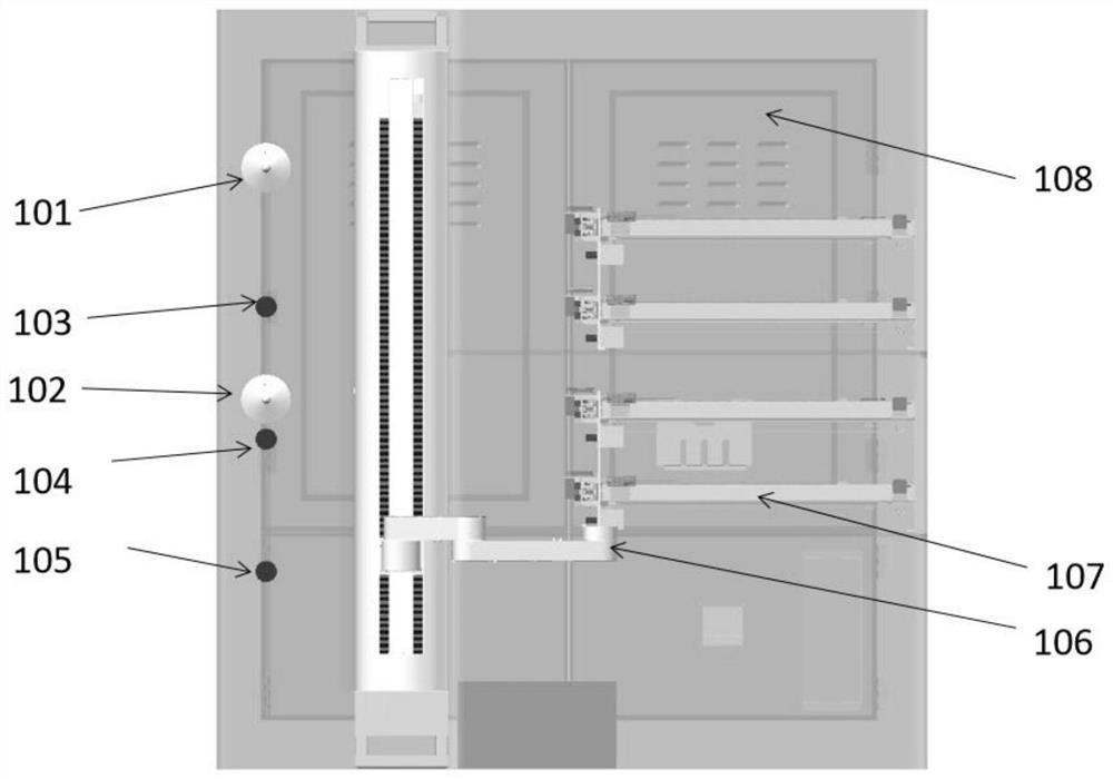
[0030] The device for accurately locating the issuing point in the present invention is as attached figure 1 As shown, it includes a cabinet body 108, and a camera, a rangefinder, a robot arm 106, and a card issuing unit located in the cabinet body 108, wherein the card issuing unit includes a card outlet and a card slot 107, and multiple cards are placed in the card slot 107, The cards in the card slot 107 are output through the card outlet one by one, and the robot arm 106 can move up, down, left, and right, and after positioning, the card in the card outlet is delivered to the positioned card issuing point. Preferably, the camera can be a plurality of cameras located on different levels, specifically as attached figure 1...


PUM


Abstract

The invention discloses a method for accurately locating a card issuing point. The method comprises the following steps: S01, enabling a camera to shoot the position of a card issuing point, and obtaining a card issuing point image; S02, acquiring coordinates of the card issuing point in an image two-dimensional coordinate system by a control center according to the card issuing point image; S03,converting card issuing point coordinates in the image two-dimensional coordinate system into card issuing point coordinates in the imaging coordinate system by the control center; S04, converting card issuing point coordinates in the imaging coordinate system into card issuing point coordinates in a camera coordinate system by the control center; S05, converting card issuing point coordinates inthe camera coordinate system into card issuing point coordinates in a world coordinate system by the control center; S06, measuring a distance between the card issuing point and the robot arm and transmitting the distance to the control center by a distance measuring instrument, and obtaining the coordinates of the card issuing point in the world coordinate system by the control center; and S07, transferring the card to a card issuing point by the arm of the robot. Accurate positioning of external three-dimensional space coordinates can be realized, and the most comfortable card issuing pointposition of a driver can be acquired so that user experience can be enhanced.

Description

technical field [0001] The invention relates to the field of automation equipment, in particular to a method for precisely locating card issuing points. Background technique [0002] At present, the windows of high-speed toll stations all adopt the mode of manually handing over the card, and the toll card is manually handed over to the driver; with the development of mechanical automation technology, automatic card issuing machines have also begun to be used in the prior art to issue cards, but the existing automatic card issuing machines The driver needs to use the card-taking button to take the card by himself. The parking distance is a little far away, and the arm can only reach the position where the card is taken, but the button on the card issuing machine cannot be pressed, so the driver has to stretch his arm as far as possible or get out of the car to take the card. This kind of non-smart The optimized operation makes it take longer for the driver to get the card, wh...

Claims


Application Information

Patent Timeline
Patent Type & Authority Applications(China)
IPC IPC(8): G07B15/06G01S17/08B25J9/10B25J18/00
CPCB25J9/10B25J18/00G01S17/08G07B15/06
Inventor 何幕峰曹端贵蒋思怡
Owner 上海福赛特智能科技有限公司
Why Eureka
Try Eureka