
Driving lane judgment method based on perception of objects around vehicle

A technology for driving roads and vehicles, applied in the field of driving lane judgment based on the perception of objects around the vehicle, it can solve problems such as the inability to realize lane-level positioning, fail to meet safety requirements, and lack of robustness, and achieve great promotion value and judgment method simple, simple effect

Inactive Publication Date: 2020-11-06
VOYAH AUTOMOBILE TECH CO LTD
View PDF5 Cites 2 Cited by
  • Summary
  • Abstract
  • Description
  • Claims
  • Application Information

AI Technical Summary

Problems solved by technology

First, high-precision maps, high-precision positioning, and lidar require high costs, which is not conducive to the popularization of high-level intelligent / automatic driving mass-produced vehicles at this stage; second, the robustness is insufficient, that is, when RTK, vision, etc. fail Lane-level positioning cannot be achieved, and it does not meet the safety requirements of high-level intelligent / automatic driving functions

Method used


Image

  • Driving lane judgment method based on perception of objects around vehicle
  • Driving lane judgment method based on perception of objects around vehicle

Examples


Embodiment 1

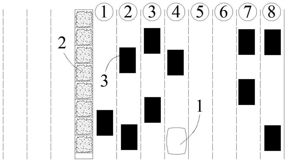
[0023] Embodiment 1: The vehicle 1 is running on a closed road, and the center of the road is separated by a central isolation belt, such as figure 1 Shown, the road of present embodiment is one-way eight lanes. The vehicle 1 has an on-board sensor. The on-board sensor in this embodiment is a millimeter-wave radar and a smart camera, which are used to sense information about objects on the left and right sides of the vehicle 1 .

[0024] The ADAS map or the car navigation map gives information on the number of lanes of the road the vehicle is driving on.

[0025] The control system recognizes the static object 2 on the left side of the vehicle 1 according to the on-board sensor. The static object 2 can be a central isolation belt, a guardrail or a signal sign. There is a central isolation belt in the middle of the road in this embodiment, so the vehicle 1 is identified by the sensor For the median on the left, the on-board sensor recognizes the positional relationship between...

Embodiment 2

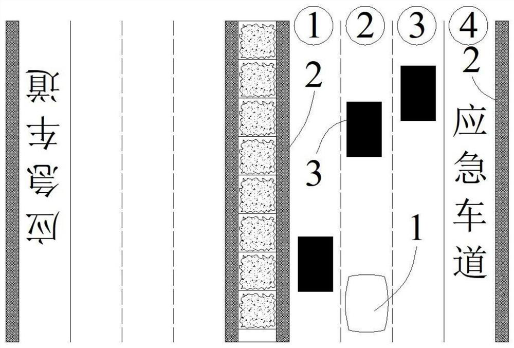
[0030] Embodiment 2: This vehicle 1 travels on domestic common highways, such as figure 2 As shown, each driving direction contains three driving lanes and one emergency lane, each driving direction is separated by isolation guardrails on both sides, and the center of the road is separated by a central isolation belt. The vehicle 1 has an on-board sensor. The on-board sensor in this embodiment is a millimeter-wave radar and a smart camera, which are used to sense information about objects on the left and right sides of the vehicle 1 .

[0031] The ADAS map or the car navigation map gives information on the number of lanes of the road on which the own vehicle 1 is traveling.

[0032] The control system recognizes the static object 2 on the left side of the vehicle 1 according to the on-board sensor. The static object 2 can be a central isolation belt, a guardrail or a signal sign. There is a guardrail on the left side of the road in this embodiment, so the sensor identifies th...


PUM


Abstract

The invention relates to the technical field of automobile control, and in particular relates to a driving lane judgment method based on perception of objects around a vehicle. The method comprises the steps of obtaining the number of lanes of a vehicle driving road, recognizing objects on the left and right sides of the vehicle, obtaining the relative position relation between the objects and thevehicle, and judging the driving lane position of the vehicle according to the relative position relation between the objects on the left and right sides of the vehicle and the vehicle and the numberof lanes. The judgment method is extremely simple, the input cost is extremely low, the vehicle lane information can be accurately judged without a high-precision map, and the method has a great popularization value.

Description

technical field [0001] The invention relates to the technical field of automobile control, in particular to a method for judging a driving lane based on the perception of objects around the vehicle. Background technique [0002] In order to realize high-level intelligent / autonomous driving functions in closed road scenarios, lane-level positioning is crucial. At this stage, the mainstream method for realizing lane-level positioning mainly relies on high-cost positioning equipment such as high-precision maps, GNSS, RTK, and high-precision inertial navigation, as well as fusion and matching of visual and lidar perception information with high-precision maps. First, high-precision maps, high-precision positioning, and lidar require high costs, which is not conducive to the popularization of high-level intelligent / automatic driving mass-produced vehicles at this stage; second, the robustness is insufficient, that is, when RTK, vision, etc. fail Lane-level positioning cannot be ...

Claims


Application Information

Patent Timeline
IPC IPC(8): G08G1/01G08G1/09G08G1/0962G08G1/0967G08G1/0968
CPCG08G1/0104G08G1/0116G08G1/0129G08G1/09G08G1/09626G08G1/096708G08G1/0968
Inventor 凃圣偲沈忱刘会凯刘继峰方维才
Owner VOYAH AUTOMOBILE TECH CO LTD
Learn More