Multidirectional conveying stacking machine

A transmission code, multi-directional technology, applied in the direction of stacking, transportation and packaging of objects, can solve the problems of the limited position of the conveyor belt and the stacking machine, increase the cost of stacking, and affect the efficiency of stacking, so as to improve the coordination Flexibility, reduction of stacking cost, and improvement of stacking efficiency

Inactive Publication Date: 2020-11-10
HANGZHOU XIANZE TECH
View PDF0 Cites 0 Cited by
  • Summary
  • Abstract
  • Description
  • Claims
  • Application Information

AI Technical Summary

Problems solved by technology

[0002] The stacker is used to stack the products conveyed by the front conveyor belt. It needs to be equipped with a stacking platform, multiple transmission mechanisms that cooperate with the stacking platform, and a set of pick-and-place mechanisms for product pick-and-place. The transmission mechanism of the stacker usually includes a front and rear transmission mechanism, an up and down transmission mechanism and a left and right transmission mechanism. However, in order to ensure the strength and transmission stability of the front and rear transmission mechanisms, the transmission in the front and rear direction usually has only one level of transmission. Therefore, the front conveyor belt needs to be Close to the stacker, not only the matching position between the conveyor belt and the stacker is limited, but also the width of the conveyor belt is l...

Method used


Image

  • Multidirectional conveying stacking machine
  • Multidirectional conveying stacking machine
  • Multidirectional conveying stacking machine

Examples


Embodiment Construction

[0038] The present invention will be described in further detail below in conjunction with the accompanying drawings, but it is not intended to limit the protection scope of the present invention.

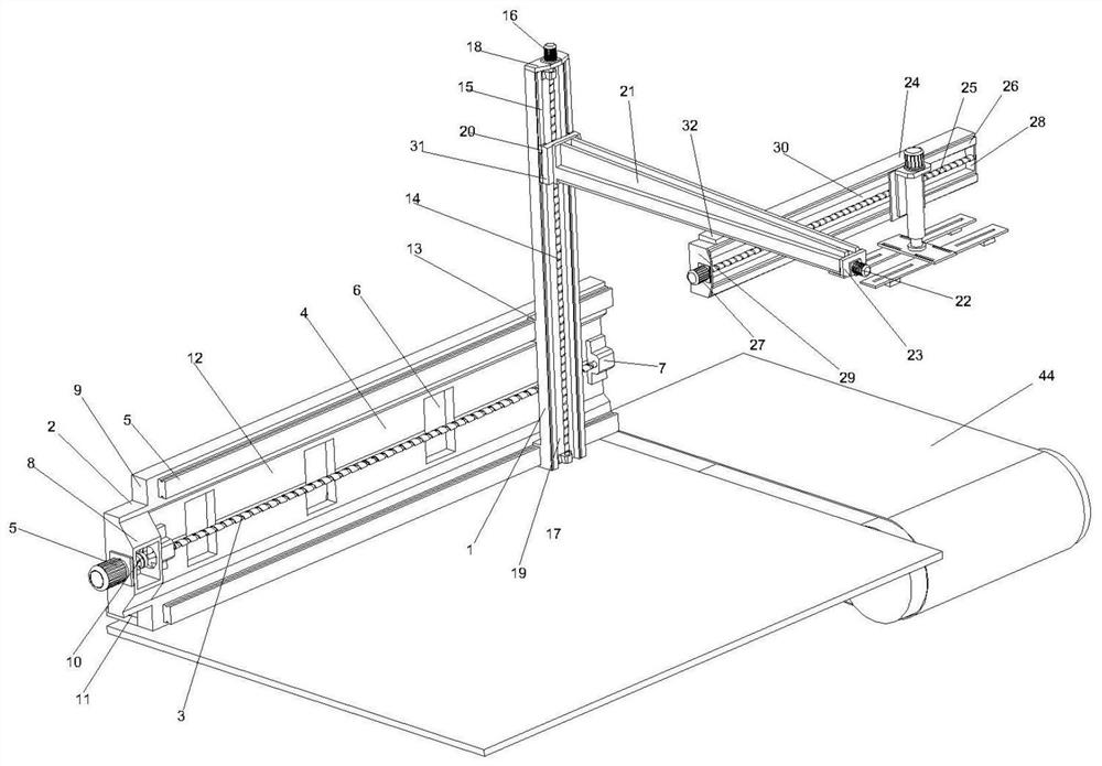
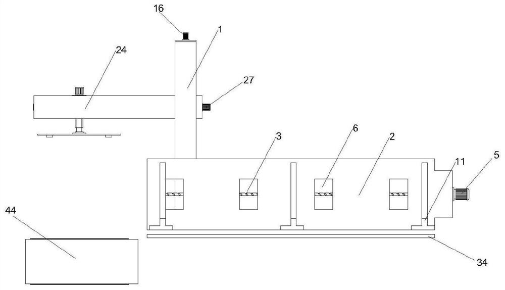
[0039] Such as figure 1 and 2 As shown, a multi-directional conveying and stacking machine includes a stacking platform 34, a conveying mechanism located on one side of the stacking platform 34, and a pick-and-place mechanism installed on the conveying mechanism. The upper and lower transmission mechanisms connected to the first-level front and rear transmission mechanisms, the left and right transmission mechanisms slid up and down connected to the upper and lower transmission mechanisms, and the second-level front and rear transmission mechanisms slid left and right connected to the left and right transmission mechanisms. On the front and rear transmission mechanism,

[0040] The first-level front and rear transmission mechanism includes a support vertical plate 2, a first-leve...


PUM


Abstract

The invention discloses a multidirectional conveying stacking machine. The multidirectional conveying stacking machine comprises a stacking table, a conveying mechanism located on one side of the stacking table and a taking and placing mechanism installed on the conveying mechanism, wherein the conveying mechanism comprises a primary front-back conveying mechanism, an up-down conveying mechanism connected to the primary front-back conveying mechanism in a front-back sliding mode, a left-right conveying mechanism connected to the up-down conveying mechanism in an up-down sliding mode, and a secondary front-back conveying mechanism connected to the left-right conveying mechanism in a left-right sliding mode, and the taking and placing mechanism is connected to the secondary front-back conveying mechanism in a front-back sliding mode. According to the multidirectional conveying stacking machine, multidirectional conveying can be achieved, the distance between the stacking machine and a front conveying belt can be properly adjusted, and the matching flexibility is improved; in addition, the conveying position of the front-back conveying mechanism can well correspond to the stacking position on the stacking table, it is guaranteed that stacked products can be well aligned, and the stacking efficiency is improved; and the multidirectional conveying stacking machine can adjust the suction width and the suction length, is suitable for products with various specifications, can adjust the direction of the products, is convenient and fast in operation, and reduces the stacking cost.

Description

technical field [0001] The invention relates to a product stacking device, in particular to a multi-directional conveying stacker. Background technique [0002] The stacker is used to stack the products conveyed by the front conveyor belt. It needs to be equipped with a stacking platform, multiple transmission mechanisms that cooperate with the stacking platform, and a set of pick-and-place mechanisms for product pick-and-place. The transmission mechanism of the stacker usually includes a front and rear transmission mechanism, an up and down transmission mechanism and a left and right transmission mechanism. However, in order to ensure the strength and transmission stability of the front and rear transmission mechanisms, the transmission in the front and rear direction usually has only one level of transmission. Therefore, the front conveyor belt needs to be Close to the stacker, not only the matching position between the conveyor belt and the stacker is limited, but also th...

Claims


Application Information

Patent Timeline
IPC IPC(8): B65G57/20B65G57/32
CPCB65G57/20B65G57/32
Inventor 陈兴淦毛志国
Owner HANGZHOU XIANZE TECH
Why Eureka
Try Eureka