Deep water offshore wind power bucket foundation mounting device and method

A technology of installation device and cylindrical foundation, which is applied in the field of installation device for deep-water offshore wind power cylindrical foundation, can solve problems such as hidden risks, high center of gravity, large wind and waves, etc., and achieve the effect of improving installation efficiency

Pending Publication Date: 2020-11-10
TIANJIN UNIV
View PDF0 Cites 3 Cited by
  • Summary
  • Abstract
  • Description
  • Claims
  • Application Information

AI Technical Summary

Problems solved by technology

Since the "one-step" installation requires the foundation, the tower, the nose of the whole machine to tow, sink, and the center of gravity is relatively high, the sinking speed, inclination angle and attitude control requirements during the sinking process are very high (the inclination angle generally cannot exceed 0.5 %); however, the deep sea environment does not need to be shallow sea environment, the wind and waves are stronger, and the current speed is faster; in addition, due to the large size of the towing vessel (floating vessel) with a cylindrical foundation, it is usually impossible to realize the safety and security of the towage to sinking process. Fast and effective connection, resulting in many hidden risks in the process of towing and sinking of the cylindrical foundation tube

Method used


Image

  • Deep water offshore wind power bucket foundation mounting device and method
  • Deep water offshore wind power bucket foundation mounting device and method
  • Deep water offshore wind power bucket foundation mounting device and method

Examples


Embodiment Construction

[0034] The present invention will be further elaborated below according to specific embodiments.

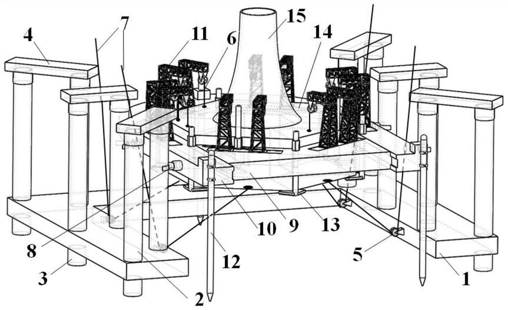
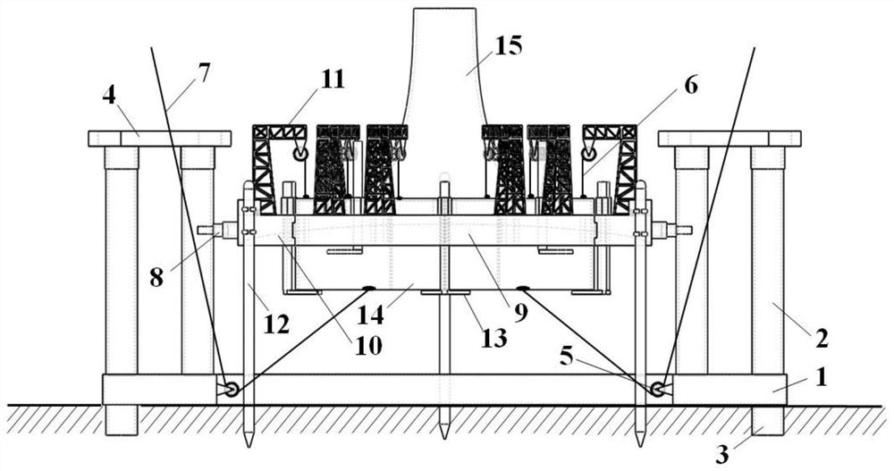
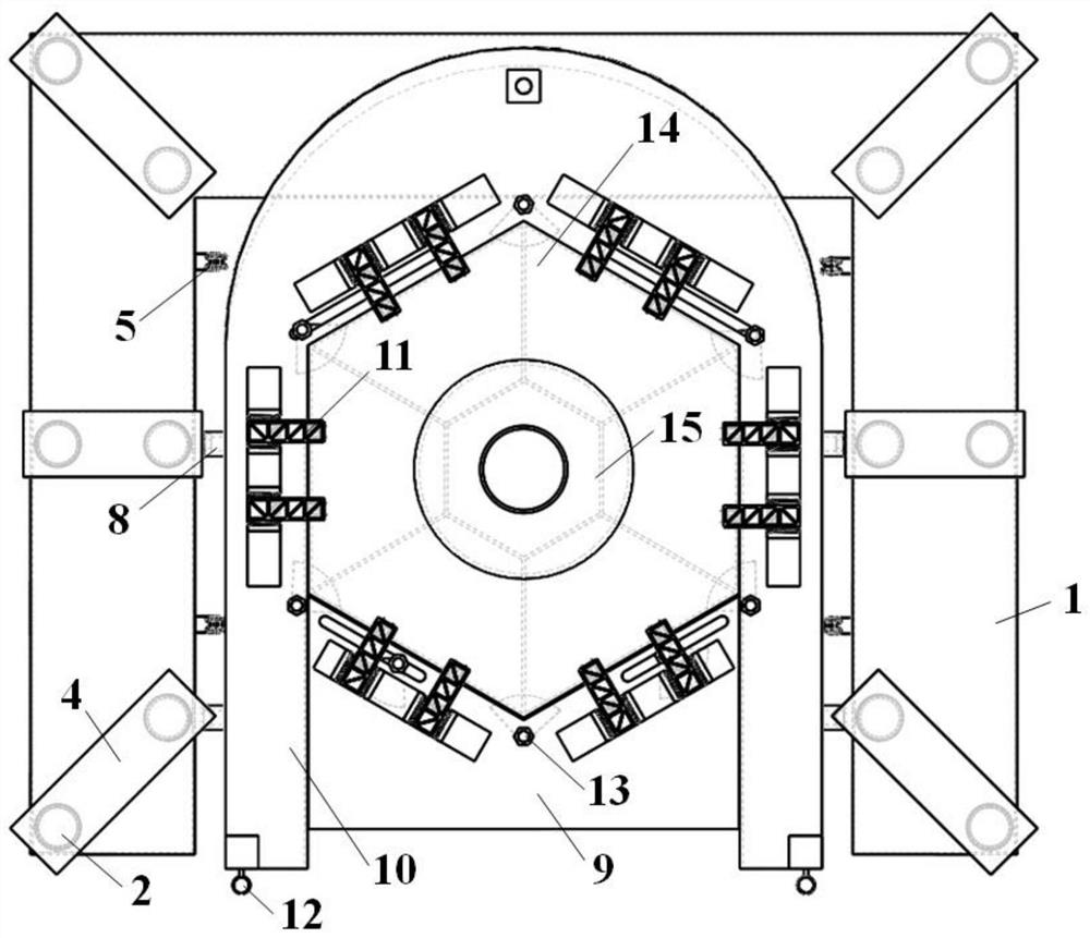
[0035] like Figure 1-6 The deep-water offshore wind power cylinder-type foundation installation device shown includes a sinking pad 1, a floating main body and a cable assembly. The lower surface of the sinking pad 1 is provided with a slot 3, and the upper surface of the sinking pad 1 is provided with a column 2. Top beam 4 is arranged on the top. Every two upright columns 2 form a group, and a top beam 4 is arranged on the top of each group of upright columns 2 . The shape of sinking pad 1 is "U". The sinking pad 1 is a hollow steel box structure. There are air holes on the sinking pad 1. The air pump can inflate the sinking pad 1 through the air holes. The water pump can inflate the sinking pad 1 through the air holes. The pad 1 drains water and is used to deflate the sinking pad 1 before sinking and inflate the sinking pad 1 before floating. The inner wall of the sinking p...


PUM


Abstract

The invention provides a deep water offshore wind power bucket foundation mounting device and method. The device comprises a sinking pad, a floating transportation main body and a mooring rope assembly; fixed pulleys are arranged on the inner side wall of the sinking pad; the floating transportation main body comprises a K-shaped floating transportation ship and a U-shaped floating transportationship, wherein the K-shaped floating transportation ship is embedded into the inner contour of the U-shaped floating transportation ship, positioning piles are arranged on the bow and the stern of theU-shaped floating transportation ship, hoops are arranged on the outer wall of the U-shaped floating transportation ship, and hanging brackets are arranged on the K-shaped floating transportation shipand the U-shaped floating transportation ship; and the mooring rope assembly comprises upward pulling righting mooring ropes and downward pulling mooring ropes, one ends of the upward pulling righting mooring ropes are connected with the hanging brackets, the other ends of the upward pulling righting mooring ropes are connected with the top of a hexagonal bucket foundation, the downward pulling mooring ropes bypass the fixed pulleys, one ends of the downward pulling mooring ropes are connected with floating balls, and the other ends of the downward pulling mooring ropes are connected with thebottom of the hexagonal bucket foundation. According to the device and method, the safety and stability of the hexagonal bucket foundation in the sinking process are guaranteed.

Description

technical field [0001] The present invention relates to the technical field of offshore wind power foundation installation, and more specifically, to a device and method for installing a deep-water offshore wind power cylinder-type foundation. Background technique [0002] At present, the foundation structures most used in offshore wind power are pile foundation structures and gravity foundation structures. However, with the development of geotechnical technology in recent years, the application range of cylindrical foundation structures in the field of offshore wind power has become more and more extensive. Compared with the traditional pile foundation structure, the cylindrical foundation is constructed by negative pressure sinking, the foundation structure has strong anti-overturning ability, and has the "one-step" installation function of the whole machine. The so-called "one-step" installation means that the basic structure, tower, and nose can be prefabricated and ins...

Claims


Application Information

Patent Timeline
IPC IPC(8): E02D27/42F03D13/20F03D13/25E02D23/08
CPCE02D23/08E02D27/425E02D2200/1657F03D13/22F03D13/25Y02E10/72Y02E10/727
Inventor 练继建刘润董霄峰燕翔王孝群
Owner TIANJIN UNIV
Why Eureka
Try Eureka