
Novel electric control valve structure

An electric control valve, a new type of technology, applied in the field of hydraulic valves, can solve the problems of hydraulic oil that cannot be hydraulically balanced, achieve smooth oil flow, prevent dry grinding damage, and reduce adjustment resistance.

Pending Publication Date: 2020-11-10
宁波保税区海天智胜金属成型设备有限公司
View PDF1 Cites 0 Cited by
  • Summary
  • Abstract
  • Description
  • Claims
  • Application Information

AI Technical Summary

Problems solved by technology

[0010] The purpose of the present invention is to provide a new type of electric regulating valve structure to solve the problem that the hydraulic oil cannot pass through the limit ejector rod when the limit ejector rod rotates to the top in the prior art. The technical problem of hydraulic balance realized by colluding oil circuit on

Method used


Image

  • Novel electric control valve structure
  • Novel electric control valve structure

Examples


Embodiment Construction

[0039] The following will clearly and completely describe the technical solutions in the embodiments of the present invention with reference to the accompanying drawings in the embodiments of the present invention. Obviously, the described embodiments are only some, not all, embodiments of the present invention. Based on the embodiments of the present invention, all other embodiments obtained by persons of ordinary skill in the art without making creative efforts belong to the protection scope of the present invention.

[0040]In the present invention, for a clearer description, the following explanations are made: the terms "longitudinal", "transverse", "upper", "lower", "front", "rear", "left", "right", " The orientation or positional relationship indicated by "vertical", "horizontal", "top", "bottom", "inner", "outer", etc. is based on the orientation or positional relationship shown in the drawings, which are only for the convenience of describing the present invention and...


PUM


Abstract

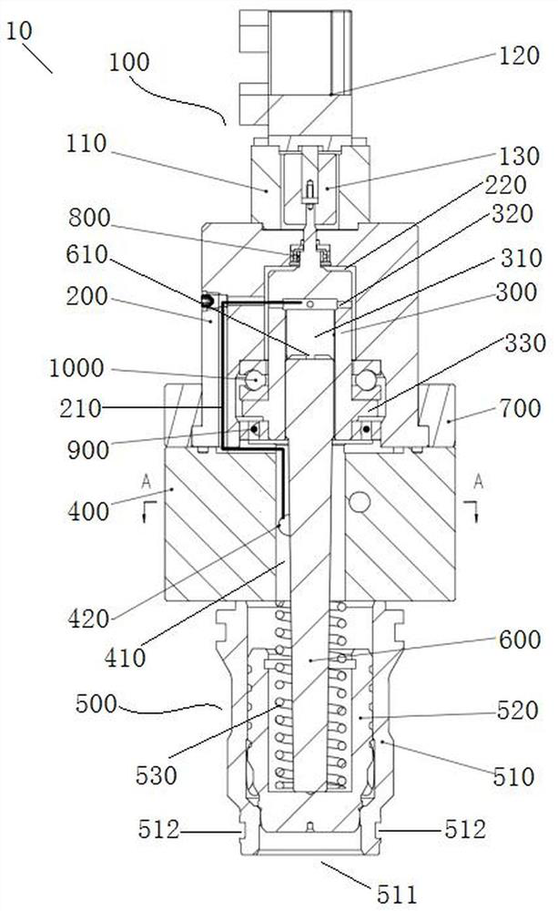
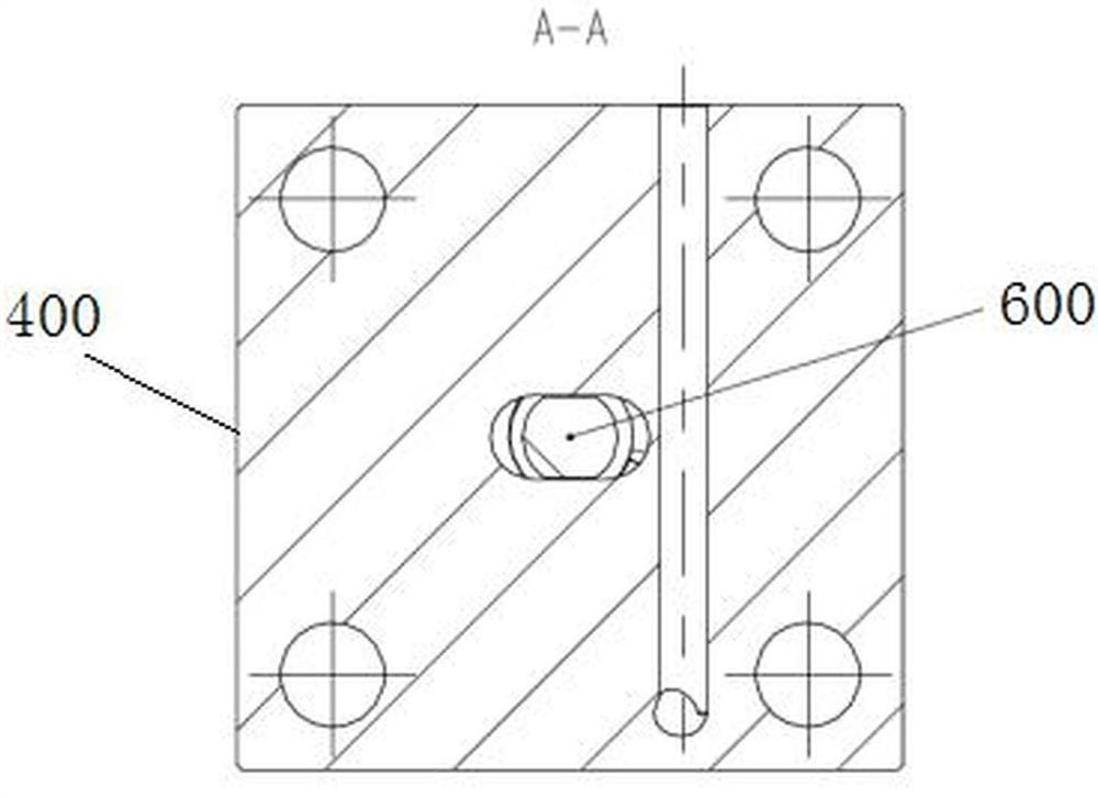
The invention discloses a novel electric control valve structure which comprises a shell, an adjusting shaft, a rotary driving assembly, a base, a cartridge valve and a limiting ejector rod. A first cavity is formed between the adjusting shaft and the shell, a second cavity is formed in the base, a first oil inlet hole is formed in the side wall of the second cavity, and a series connection oil way is formed in the shell and communicates with the first cavity and the second cavity; a third cavity is formed between the limiting ejector rod and the adjusting shaft, a second oil inlet hole is formed in the side wall of the third cavity, the second oil inlet hole communicates with the first cavity and the third cavity, the lower end of the limiting ejector rod penetrates through the second cavity and is inserted into the cartridge valve, and the limiting ejector rod controls the maximum opening degree of a valve body of the cartridge valve; and a first shape and a second shape are matchedto limit the limiting ejector rod to only move linearly but not rotate. Upper and lower structure hydraulic balance of a cartridge valve control cavity is achieved by the external circulation of the series connection oil way, and dry grinding damage of part of components is prevented, so that the purpose of reducing the adjusting resistance is achieved.

Description

technical field [0001] The invention relates to the technical field of hydraulic valves, in particular to a novel electric regulating valve structure. Background technique [0002] At present, in the die-casting machine and injection molding machine industry, the opening limit adjustment structure of the cartridge valve includes manual adjustment and electric adjustment. Threaded connection, one end of the adjusting ejector rod is inserted into the control chamber of the valve core, and the opening of the valve core is limited by manually turning the handwheel to drive the adjusting ejector rod forward or backward. The manual adjustment structure is simple, and only a part of the limit ejector rod is submerged in the hydraulic chamber connected to the control chamber of the cartridge valve core, and the hydraulic pressure received is not completely balanced. Therefore, when the oil pressure in the control chamber of the cartridge valve is high , the ejector rod bears a larg...

Claims


Application Information

Patent Timeline
IPC IPC(8): F16K31/04F16K31/50F16K1/52F16K29/00
CPCF16K1/52F16K29/00F16K31/047F16K31/50
Inventor 刘亮金海彪叶国良张学文周益刚
Owner 宁波保税区海天智胜金属成型设备有限公司
Learn More