Pipeline connecting structure and gas stove

A connection structure and gas stove technology, which is applied in the direction of sleeve/socket connection, pipe/pipe joint/pipe fitting, passing element, etc., can solve the problem of low disassembly and assembly efficiency, and achieve the effect of high disassembly and assembly efficiency

Pending Publication Date: 2020-11-10
HANGZHOU ROBAM APPLIANCES CO LTD
View PDF0 Cites 0 Cited by
  • Summary
  • Abstract
  • Description
  • Claims
  • Application Information

AI Technical Summary

Problems solved by technology

[0005] The purpose of the present invention is to provide a pipeline connection structure and a gas stove, so as to alleviate

Method used


Image

  • Pipeline connecting structure and gas stove
  • Pipeline connecting structure and gas stove
  • Pipeline connecting structure and gas stove

Examples


Embodiment Construction

[0039] The technical solutions of the present invention will be clearly and completely described below in conjunction with the accompanying drawings. Apparently, the described embodiments are some of the embodiments of the present invention, but not all of them. Based on the embodiments of the present invention, all other embodiments obtained by persons of ordinary skill in the art without making creative efforts belong to the protection scope of the present invention.

[0040] In the description of the present invention, it should be noted that the orientation or positional relationship indicated by the terms "inner", "outer" and the like are based on the orientation or positional relationship shown in the drawings, and are only for the convenience of describing the present invention and simplifying the description. It is not intended to indicate or imply that the referred device or element must have a particular orientation, be constructed in a particular orientation, and ope...


PUM


Abstract

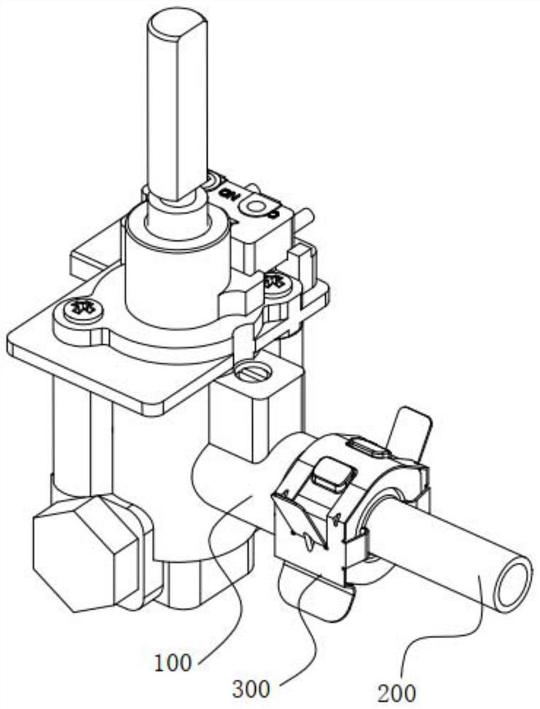
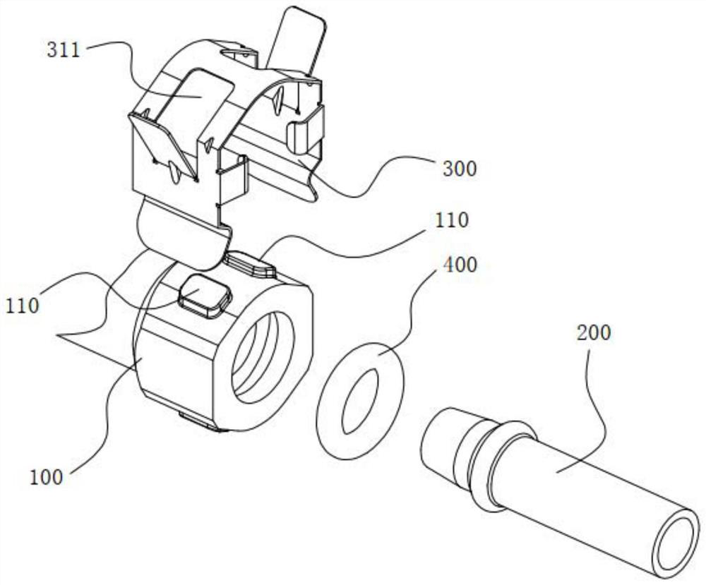
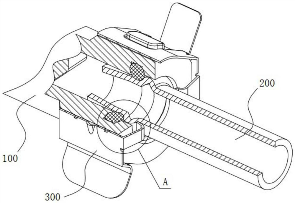
The invention relates to the field of pipeline connection, in particular to a pipeline connecting structure and a gas stove. The pipeline connecting structure comprises a first pipeline, a second pipeline and a connecting piece, wherein the second pipeline communicates with the first pipeline; the connecting piece is provided with a clamping groove, and the first pipeline can be clamped into the clamping groove; one of the connecting piece and the first pipeline is provided with a positioning block, the other of the connecting piece and the first pipeline is provided with a positioning groove,and the positioning block is matched with the positioning groove so as to limit movement of the connecting piece relative to the first pipeline; and a limiting protrusion is arranged on the outer pipe wall of the second pipeline, a clamping jaw is arranged on the connecting piece, and the clamping jaw is matched with the limiting protrusion in a clamped mode so as to limit movement of the secondpipeline relative to the first pipeline. The gas stove comprises the pipeline connecting structure. According to the pipeline connecting structure and the gas stove, the disassembly and assembly efficiency of every two adjacent pipelines is high.

Description

technical field [0001] The invention relates to the field of pipeline connection, in particular to a pipeline connection structure and a gas stove. Background technique [0002] Many of the passages used to transport fluids are formed by several pipelines, and two adjacent pipelines (for example: the valve body outlet pipe and gas distribution pipe of the gas stove) are generally connected together by threaded connection. To realize the communication between pipelines. [0003] On the one hand, the threaded connection is difficult to operate, resulting in low disassembly and assembly efficiency between pipelines; on the other hand, the thread itself may have problems of missing teeth and deformation. In addition, there is a risk of slipping teeth during product assembly. Therefore, the pipe The pipeline is easily unusable due to the defect of the thread, and the damaged pipeline needs to be replaced, which further reduces the assembly efficiency. [0004] To sum up, how to...

Claims


Application Information

Patent Timeline
IPC IPC(8): F16L21/08
CPCF16L21/08
Inventor 任富佳王坚陈六明颜运宇
Owner HANGZHOU ROBAM APPLIANCES CO LTD
Why Eureka
Try Eureka