Folding working lamp

A technology for working lamps and folding poles, applied in lighting and heating equipment, portable lighting devices, with built-in batteries, etc., to achieve the effects of cost control, compact structure, and reduced packaging and transportation volume

Pending Publication Date: 2020-11-10
HANGZHOU UNITED ELECTRIC MFG CO LTD
View PDF1 Cites 6 Cited by
  • Summary
  • Abstract
  • Description
  • Claims
  • Application Information

AI Technical Summary

Problems solved by technology

However, this utility model is only connected to part of the structure of the lamp body, while other structures of the lamp body are still relatively independent from the bracket, so there is still a space for cooperation between the bracket and the lamp body to be further optimized

Method used


Image

  • Folding working lamp
  • Folding working lamp
  • Folding working lamp

Examples


Embodiment 1

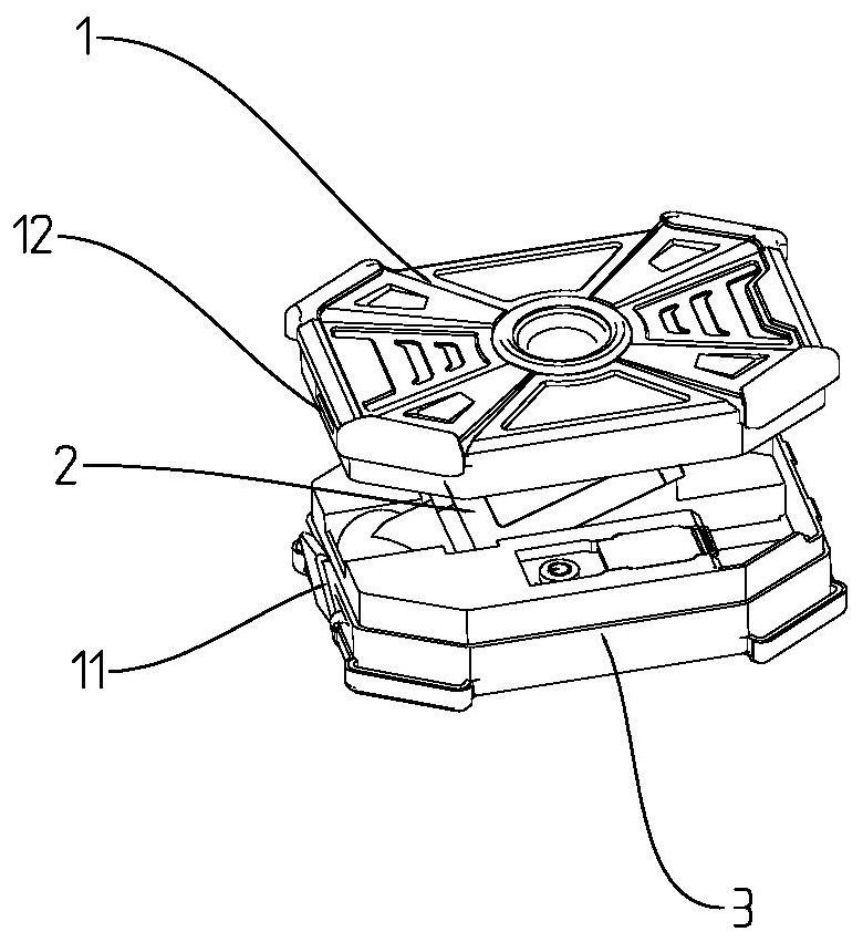
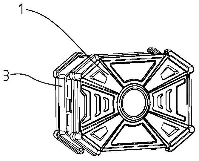
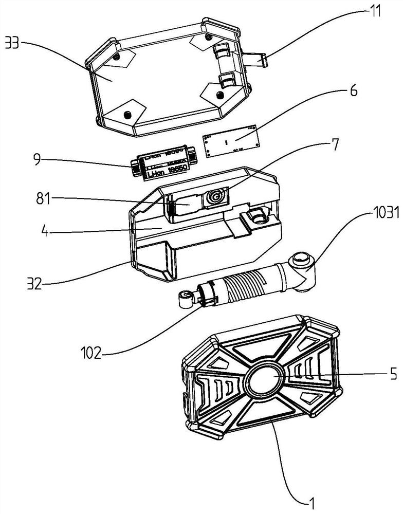
[0032] Such as Figure 1 to Figure 7 As shown, a foldable work light includes a lamp body and a bracket 2, the lamp body includes a lighting part 1 and a support part 3, and the support part 3 of the lamp body is provided with an accommodating space 4 for accommodating the bracket 2, accommodating The space 4 is in the shape of a groove. One end of the bracket 2 is connected to the lighting unit 1 , and the other end is connected to the support unit 3 . The bracket 2 is an adjustable part. In this embodiment, the bracket 2 is a telescopic rod, including a seven-section sleeve. The sleeve is in the shape of a truncated cone. Decreasing and nested connections, that is, the diameter of the sleeve connected to one end of the support part 3 is the largest, and the diameter of the sleeve connected to the end of the lighting part 1 is the smallest. The bracket 2 is rotatably connected with the lighting part 1, so that the lighting part 1 can be adjusted 360° relative to the bracket...

Embodiment 2

[0035] The support 2 includes four sleeve pipes, and the sleeve pipes are screwed together. The support 2 in the form of a telescopic rod can be adjusted to any length within the telescopic range. All the other are with embodiment 1.

[0036]If the length of the support 2 needs to be adjusted, each segment of the casing can be rotated separately to convert the rotation of the casing into the variation of the axial position. When the support 2 reaches the required length, the rotation can be stopped, and each joint sleeve pipe stays on the position adjusted to at last.

Embodiment 3

[0038] Such as Figure 8 , Figure 9 As shown, the bracket 2 is a foldable rod, including five tubular rods, and each tubular rod is hinged sequentially through hinges, that is, the head end of the tubular rod is connected to the tail end of the previous tubular rod, and all the tubular rods pass through the tension rope inside the tubular rod. 13 in series, the head end of the tension rope 13 is connected to the lighting part 1, the end of the tension rope 13 is wound on a rope shaft located at the support part 3, and the rope winding shaft is connected to the support part 3 in rotation and positioned by the ratchet ratchet structure . The included angle between adjacent tubular rods changes between 0-180°, and when it reaches 180°, it is limited by the hinge and does not change anymore. The hinge constrains the rear end of the connecting part of the adjacent tubular rod, and the connecting part of the adjacent tubular rod is provided with a tenon-tenon hole matching struct...


PUM


Abstract

The invention discloses a folding working lamp which comprises a lamp body and a support, and the lamp body is provided with a containing space capable of containing the support. The lamp body can turn over around the rotating shaft, rotate around the axis of the lamp body and rotate in the two different rotating faces, and through combination of different angles in the different rotating faces, the lamp body can obtain more abundant positions and directions, so that more lighting directions and lighting areas are provided, and different lighting requirements are met. The lamp body can be stored in the support, compact packaging of products is facilitated, the packaging and transporting size is reduced, and the product loading and transporting cost is reduced.

Description

technical field [0001] The present invention relates to a light fixture, and more particularly, to a folding work light. Background technique [0002] When working outdoors or in relatively open places, lighting tools need stable installation support to achieve the required lighting height and angle. The lamp body and bracket of the existing work lights with brackets are usually split structures, and the volume is relatively large. Large, combined installation takes a certain amount of time, and it is not convenient to carry. For this reason, some types of foldable work lights have been introduced on the market, which can combine the bracket and the light body more compactly, thereby reducing the volume and making it easy to use. For example, the utility model patent with the publication number CN204187295U disclosed a bracket-type work lamp on March 4, 2015, including a lamp body and a base as a bracket. The lamp body is connected to the base through a telescopic rod, and ...

Claims


Application Information

Patent Timeline
Patent Type & Authority Applications(China)
IPC IPC(8): F21L4/00F21V21/30F21V21/22F21V21/14
CPCF21L4/00F21V21/14F21V21/22F21V21/30
Inventor 王伟毅
Owner HANGZHOU UNITED ELECTRIC MFG CO LTD
Why Eureka
Try Eureka