Movable vibration exciter for simulating train load and loading method thereof

A kind of train simulation, mobile technology, applied in the field of mobile vibration exciter and its loading, can solve the problems of low fidelity and difficult loading, and achieve the effect of wide application prospect and strong expansibility

Pending Publication Date: 2020-11-10
CHANGAN UNIV
0 Cites 1 Cited by

AI-Extracted Technical Summary

Problems solved by technology

[0004] Aiming at the technical problems existing in the prior art, the present invention provides a mobile vibration exciter and its loading me...

Method used

In roadbed, be provided with pressure box and acceleration sensor, the output end of pressure box and acceleration sensor is shown in external collection device connection by the data of drawing, realizes the real-time collection to roadbed dynamic characteristic.
The present embodiment provides a kind of mobile exciter for simulating train load, com...

Abstract

The invention discloses a movable vibration exciter for simulating a train load and a loading method thereof. The movable vibration exciter comprises a rail mechanism, a traction device and a vibration device, the traction device and the vibration device are both movably arranged on the rail mechanism, the rear end of the traction device is hinged to the front end of the vibration device, the traction device is used for driving the vibration device to move on the rail mechanism, and the vibration device is used for generating variable-frequency excitation force to the rail mechanism. The traction device and the vibration device are arranged on the rail mechanism, the vibration device is driven by the traction device to move on the rail mechanism, variable-frequency excitation force is generated on the rail mechanism in the moving process of the vibration device, the loading process of the vibration device can effectively simulate the real train load, and the influence of the train loadon a roadbed is analyzed; guidance can be provided for engineering construction according to dynamic response result feedback of the roadbed, the train load can be well simulated, the difficulty is low, the simulation trueness is high, and the simulation is closer to the actual situation.

Application Domain

Vibration testing

Technology Topic

Structural engineeringMotive power +2

Image

  • Movable vibration exciter for simulating train load and loading method thereof
  • Movable vibration exciter for simulating train load and loading method thereof
  • Movable vibration exciter for simulating train load and loading method thereof

Examples

  • Experimental program(1)

Example Embodiment

[0049] Example
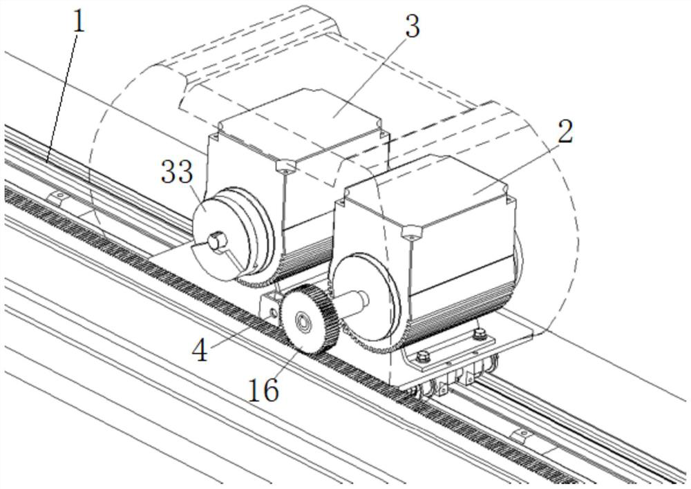
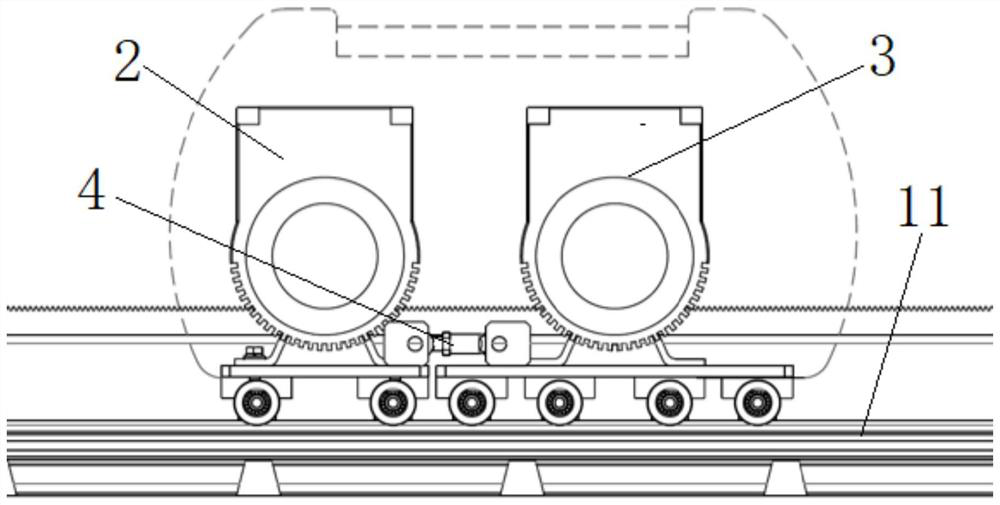
[0050] This embodiment provides a mobile vibration exciter for simulating train load, including a track mechanism and a mobile load loading device. The mobile load loading device includes a traction device, a vibration device, and a hinge connection block. The traction device and the vibration device pass through the hinge The connecting blocks are connected together, and the traction device has a traction effect on the vibration device to achieve the effect of linkage.
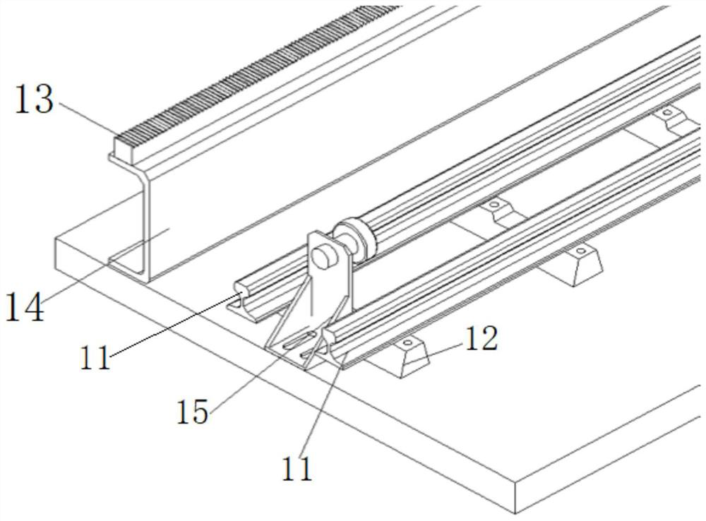
[0051] The track mechanism includes two guide rails, several sleepers, horizontal racks, channel steel, stoppers and transmission gears. The two guide rails are arranged horizontally and parallel, and several sleepers are evenly arranged under the guide rails, and the guide rails are fixed on the subgrade through the sleepers; A pressure box and an acceleration sensor are embedded in the subgrade. The pressure box is embedded in the soil under the subgrade with a depth of about 1m and is arranged longitudinally along the center line of the subgrade. The number of measuring points can be planned according to actual conditions for detecting trains. The dynamic soil pressure in the roadbed when the load moves; the acceleration sensor is embedded in the same way as the pressure box, and is arranged longitudinally along the roadbed to analyze the acceleration response in the roadbed. The sensor wiring leads to an external collection computer.
[0052] The horizontal rack is arranged in parallel on one side of the guide rail. The horizontal rack is fixedly installed on the subgrade by channel steel. The webs of the channel steel are arranged vertically. One flange plate is fixedly connected to the subgrade, and the other flange plate is connected to the horizontal tooth. The bar is fixedly connected; the transmission gear is fixedly installed at the output end of the traction device, and the transmission gear and the horizontal rack are meshed with each other; the stopper is fixedly arranged between the two guide rails and is placed at the two ends of the guide rail.
[0053] The traction device includes a transmission motor, a traction vehicle plate, two traction wheel axles and four traction wheels. The four traction wheels are respectively arranged at both ends of the two traction wheel axles. The two traction wheel axles are fixedly arranged on the traction wheel through a bearing support. Below the vehicle plate, two traction wheel axles and four traction wheels are combined to form the moving mechanism of the traction device.
[0054] The tractor board is arranged horizontally above the guide rail, and the transmission motor is fixed on the tractor board through four bolts as the driving mechanism; two traction wheel axles are arranged horizontally and parallel below the tractor board, and the traction wheel axle is arranged perpendicular to the guide rail ; Four traction wheels are installed on the guide rail in pairs; the output shaft of the transmission motor is arranged horizontally, and the transmission gear is connected with the output shaft of the transmission motor through the motor shaft sleeve.
[0055] The vibration device includes a variable frequency vibration motor, a vibrating car plate, a vibration eccentric block, four vibrating wheel shafts and eight vibrating wheels. The eight vibrating wheels are respectively arranged at both ends of the four vibrating wheel shafts, and the four vibrating wheel shafts are supported by bearings. The seat is fixedly arranged under the tractor board, and four vibrating wheel axles and eight vibrating wheels are combined to form a moving mechanism of the vibrating device.
[0056] The vibrating car plate is horizontally arranged above the guide rail, and the variable frequency vibration motor is fixed on the top of the vibrating car plate through four bolts; the four vibrating wheel axles are arranged horizontally and evenly under the vibrating car plate, and the vibrating wheel axle is perpendicular to the guide rail. Two vibrating wheels are respectively installed on the guide rail; the output shaft of the variable frequency vibration motor is arranged horizontally, and the vibration eccentric block is fixedly arranged on the output shaft of the variable frequency vibration motor; the front end of the vibrating car plate is connected to the rear end of the tractor plate through a hinge connection block ;
[0057] The frequency conversion vibration motor includes the motor, the worm gear box, the point relay, the shaft sleeve of the frequency conversion machine, and the shaft of the frequency conversion machine. The worm gear reduction box has a flange, which can be directly sleeved on the motor, and the shaft sleeve of the frequency conversion machine and the frequency conversion machine are connected by bolts. The shaft and motor are equipped with point relays to provide switch position indication and protection.
[0058] This embodiment controls the mass of the vibrating eccentric mass and uses its rotating unbalanced mass to generate periodic vibrations to obtain a certain amount of vibration to simulate the excitation force generated by the train on the guide rail; control the simulated train by controlling the frequency of the drive motor The higher the frequency, the faster the vehicle speed.
[0059] This embodiment also provides a loading method for simulating train load, including the following steps:
[0060] Step 1. Select the high-speed train prototype to be studied, and determine the basic parameters of the high-speed train prototype; the basic parameters include train quality, speed, track spacing, and static wheel load; determine the mobile type according to the basic parameters of the high-speed train to be studied The structure size of the exciter;
[0061] Step 2. Determine the output frequency of the mobile vibration exciter according to the relationship between the train speed of the high-speed train prototype and the loading frequency of the mobile vibration exciter, and set the rotational speed of the vibration eccentric mass;
[0062] Among them, the relationship between the train speed of the prototype high-speed train and the loading frequency of the mobile vibration exciter is as follows:
[0063] f i =v i /l i (1)
[0064] Where f i Is the load vibration frequency, Hz; v i Is the driving speed, m/s; l i Is the spacing between the loading units, that is, the spacing between the train bogies, m;.
[0065] Step 3. According to the correspondence between the train speed of the high-speed train prototype and the magnitude of the excitation force output by the mobile vibration exciter, determine the magnitude of the train excitation force that needs to be studied, and determine the mass of the eccentric wheel;
[0066] When the mobile vibration exciter works, the vibration exciter is used to output the excitation force to simulate the excitation force acting on the guide rail when the train is running; the relationship between the train speed and the excitation force Pd output by the vibration exciter is:
[0067] Pd=Ps(1+αv) (2)
[0068] Among them, Ps is the static wheel load, kN; α is the speed amplification factor, usually 0.004; v is the train speed, km/h.
[0069] When the mobile vibration exciter is working, the relationship between the output excitation force and the mass of the vibration eccentric mass and the vibration frequency:
[0070] F=mr(2πf) 2 +mg (3)
[0071] Among them, F is the excitation force, N; m is the mass of the vibrating eccentric mass, kg; r is the radius of the vibrating eccentric mass, m; f is the vibration frequency, Hz; g is the acceleration due to gravity, m/s 2.
[0072] Step 4. Assemble and debug the track mechanism and train moving load loading system;
[0073] Step 5. Turn on the power supply and start the mobile vibration exciter, run according to the preset frequency characteristics, and generate simulated train load;
[0074] Step 6. During the operation of the exciter, use pressure boxes and acceleration sensors distributed in the subgrade to study the dynamic characteristics of the subgrade.
[0075] According to the present invention, a mobile vibration exciter for simulating train load and a loading method thereof, the one-time loading and unloading process of the dynamic stress generated by the train load on the roadbed surface is completed by the joint action of two axle loads of a bogie, The adjacent bogies of the front and rear carriages of the train have obvious superposition effects, so the vibration exciter of the present invention regards the wheel axle load of the adjacent bogies of the front and rear carriages of the prototype train as a loading unit; the rotation of the eccentric wheel generates excitation load , The load can be transmitted to the subgrade base through wheels and guide rails; among them, every time the eccentric wheel rotates, the exciter will strike the rail once, that is, the exciter will vibrate once, corresponding to an excitation load; by adjusting the exciter The output frequency can be used to change the running speed of the simulated train. By controlling the mass of the eccentric mass of the exciter, the exciting force acting on the guide rail when the train is running can be simulated. When conducting model tests to study the dynamic characteristics of the subgrade under the action of the train load, this device can be used to better simulate the train load and to study the dynamic characteristics of the subgrade. The invention has convenient operation, strong practicability and strong expandability, and has broad application prospects in the field of engineering research.

PUM

no PUM

Description & Claims & Application Information

We can also present the details of the Description, Claims and Application information to help users get a comprehensive understanding of the technical details of the patent, such as background art, summary of invention, brief description of drawings, description of embodiments, and other original content. On the other hand, users can also determine the specific scope of protection of the technology through the list of claims; as well as understand the changes in the life cycle of the technology with the presentation of the patent timeline. Login to view more.

Similar technology patents

Cross-machine-room data synchronization method and system

ActiveCN110309231AReduce code duplicationStrong scalability
Owner:FOCUS TECH

Fast three-phase space vector modulation method based on three-dimensional coordinate system

ActiveCN109149983AStrong scalabilityImprove harmonic performance
Owner:SOUTHWEST JIAOTONG UNIV

Method and device for recognizing network resource entity content page

ActiveCN103605742AEfficient and accurate identificationStrong scalability
Owner:BEIJING SOGOU TECHNOLOGY DEVELOPMENT CO LTD

Mobile terminal, network set-top box based on Android and system recovery method thereof

InactiveCN104618802AStrong scalabilitySmart and precise system recovery
Owner:MEHOME DIGITAL CO LTD

M56*3 high-strength bolt production method

Owner:郑州水野大一热处理技术有限公司

Classification and recommendation of technical efficacy words

  • Broad application prospects
  • Strong scalability

Transformer substation state monitoring data standardized access system and transformer substation state monitoring data standardized access method

ActiveCN103123484AStrong scalabilityStrong secondary development capability
Owner:LIAONING ELECTRIC POWER COMPANY LIMITED POWER SCI RES INSTION +2
Why Eureka
Try Eureka