Check patentability & draft patents in minutes with Patsnap Eureka AI!

Light emitting device and display device

A light-emitting device and display device technology, applied to static indicators, instruments, etc., can solve problems such as insufficient brightness and poor display effect

Active Publication Date: 2022-01-04
INNOLUX CORP
View PDF4 Cites 0 Cited by
  • Summary
  • Abstract
  • Description
  • Claims
  • Application Information

AI Technical Summary

Problems solved by technology

[0003] Some electronic products have the function of lighting or display, but there are still problems such as insufficient brightness or poor display effect

Method used


Image

  • Light emitting device and display device
  • Light emitting device and display device
  • Light emitting device and display device

Examples


Embodiment Construction

[0016] Here, the terms "about", "approximately" and "substantially" usually mean within 20% of a given value or range, such as within 10%, within 5%, within 3%, within 2% Within, within 1%, or within 0.5%. The quantities given here are approximate quantities, that is, in the absence of specific descriptions of "about", "approximately" and "substantially", "approximately", "approximately" and "substantially" can still be implied meaning.

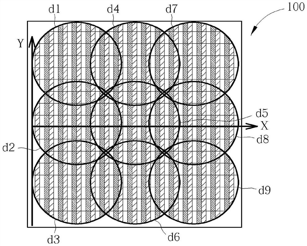
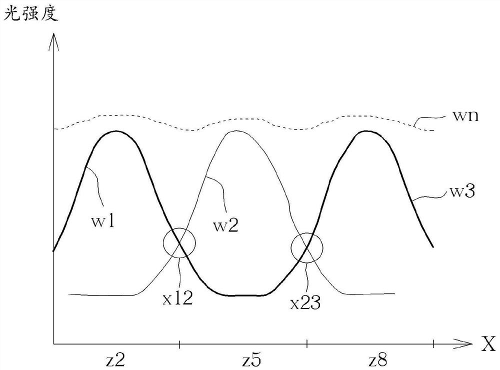
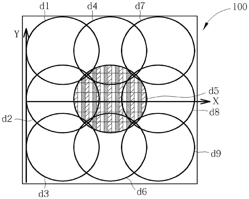
[0017] figure 1 is a schematic diagram of the display device 100 in a normal mode in an embodiment. figure 2 is corresponding to figure 1 Waveform graph of light intensity. image 3 is a schematic diagram of the display device 100 in peak mode in an embodiment. Figure 4 is corresponding to image 3 Waveform graph of light intensity.

[0018] Such as figure 1 and image 3 As shown, on the display device 100 , in the coordinates formed by the horizontal axis X and the vertical axis Y, the dimming areas d1 to d9 can be arranged and pl...


PUM


Abstract

The invention discloses a light-emitting device and a display device, wherein the light-emitting device includes a light-emitting unit, and the light-emitting unit includes a driving transistor and a light-emitting diode. The driving transistor includes a first terminal, a second terminal and a gate terminal, wherein the first terminal receives an operating voltage. The light emitting diode is coupled to the second end and used for receiving the driving current. Wherein, the operating voltage is variable.

Description

technical field [0001] The invention relates to a light emitting device and a display device, in particular to a light emitting device and a display device with a variable operating voltage. Background technique [0002] Electronic products have become an indispensable necessity in modern society. With the boom in such electronic products, consumers have high expectations regarding the quality, functionality or price of these products. [0003] Some electronic products have the function of lighting or display, but there are still problems such as insufficient brightness or poor display effect. Contents of the invention [0004] An embodiment of the present invention provides a light emitting device, which includes a light emitting unit, and the light emitting unit includes a driving transistor and a light emitting diode. The driving transistor includes a first terminal, a second terminal and a gate terminal, wherein the first terminal receives an operating voltage. The ...

Claims


Application Information

Patent Timeline
Patent Type & Authority Patents(China)
IPC IPC(8): G09G3/34
CPCG09G3/3406G09G3/3413
Inventor 陈良禄丁景隆高克毅毛立维曾名骏
Owner INNOLUX CORP
Features
  • R&D
  • Intellectual Property
  • Life Sciences
  • Materials
  • Tech Scout
  • Unparalleled Data Quality
  • Higher Quality Content
  • 60% Fewer Hallucinations
Learn More