
A digital monitoring system and method for urban road network

A technology of urban road network and monitoring system, which is applied in closed-circuit television system, stereo system, image data processing, etc. It can solve the problems of difficult retrieval, high storage cost, and high identification difficulty, so as to improve identification accuracy, reduce storage cost, The effect of reducing the difficulty of retrieval

Active Publication Date: 2021-10-19
PEKING UNIV
View PDF4 Cites 0 Cited by
  • Summary
  • Abstract
  • Description
  • Claims
  • Application Information

AI Technical Summary

Problems solved by technology

However, there are several problems in this traditional monitoring method: 1) It is difficult to identify. The most traditional identification method is to rely on human viewing and searching. This method has strong identification ability, but it is easy to miss or ignore key content due to subjective factors. The strategy is to use artificial intelligence methods such as video and image recognition algorithms, but there are also challenges in big data processing due to the long recognition time, large amount of data to be processed, and high investment costs; 2) Retrieval is difficult, and storage is conventional video The focus of the monitoring system, so the compression and encoding during the storage process may cause data loss, and the decompression and decoding when extracting data may also cause data loss. Even if the correct retrieval is performed, the original result is often not obtained; 3) The storage cost is high. The main reason for compressing data before storage is to improve memory utilization and reduce storage costs. Even so, the amount of data stored in existing video surveillance systems is still very large, and the greater the amount of data, the higher the cost. Moreover, the amount of data will inevitably show an obvious growth trend with the extension of storage time.

Method used


Image

  • A digital monitoring system and method for urban road network
  • A digital monitoring system and method for urban road network
  • A digital monitoring system and method for urban road network

Examples


Embodiment Construction

[0055] The following description and drawings illustrate specific embodiments of the invention sufficiently to enable those skilled in the art to practice them.

[0056] It should be clear that the described embodiments are only some of the embodiments of the present invention, not all of them. Based on the embodiments of the present invention, all other embodiments obtained by persons of ordinary skill in the art without creative efforts fall within the protection scope of the present invention.

[0057] When the following description refers to the accompanying drawings, the same numerals in different drawings refer to the same or similar elements unless otherwise indicated. The implementations described in the following exemplary examples do not represent all implementations consistent with the present invention. Rather, they are merely examples of apparatuses and methods consistent with aspects of the invention as recited in the appended claims.

[0058] In the descriptio...


PUM


Abstract

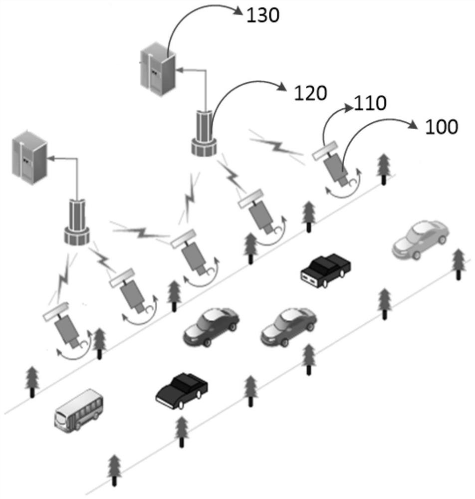
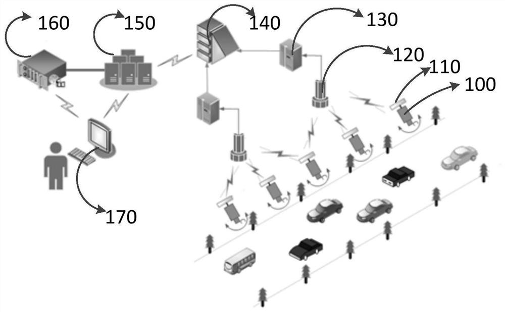
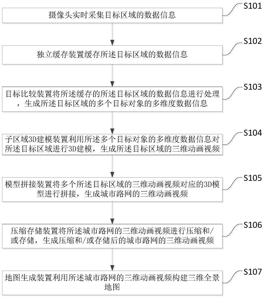
The invention discloses a system and method for digital monitoring of urban road network. The system includes: a camera for collecting data information of a target area in real time; an independent buffer device for buffering the data information of the target area; a target comparison device The method is used to obtain and process the cached data information of the target area, and generate multi-dimensional data information of multiple target objects in the target area; the sub-area 3D modeling device is used to utilize the multi-dimensional data information of the multiple target objects The dimensional data information performs 3D modeling on the target area to generate a 3D animation video of the target area. Therefore, using the embodiment of the present application, since the camera collects images to construct a 3D surveillance video for digital monitoring of the urban road network based on the digital retina, the recognition accuracy is improved, the storage cost is reduced, and the retrieval difficulty is reduced.

Description

technical field [0001] The invention relates to the technical field of security monitoring, in particular to a digital monitoring system and method for an urban road network. Background technique [0002] At present, the surveillance video network based on the electronic map has been widely used in daily urban prevention and control and command and dispatch. Through the application of the electronic map, the video surveillance of the designated place on the electronic map can be carried out in real time. Compared with the traditional monitoring platform, based on The electronic map monitoring platform can provide better user experience, more real-time point monitoring, more intuitive presentation, and smarter. [0003] Existing video surveillance systems are basically designed for storage considerations. When it is necessary to retrieve a video of a certain time period and a certain location, it will be retrieved from the massive video storage, and then retrieved from the se...

Claims


Application Information

Patent Timeline
Patent Type & Authority Patents(China)
IPC IPC(8): H04N7/18H04N13/275G06T17/05
CPCG06T17/05H04N7/18H04N13/275
Inventor 马思伟
Owner PEKING UNIV
Learn More