Chamfering device for circuit board production

A technology of chamfering device and circuit board, which is applied in the direction of circuit board tool positioning, printed circuit, printed circuit manufacturing, etc., can solve problems such as poor fixing stability of the board, and achieve the effects of ensuring stability, reducing friction and improving fluency.

Inactive Publication Date: 2020-11-10
刘财英
View PDF0 Cites 0 Cited by
  • Summary
  • Abstract
  • Description
  • Claims
  • Application Information

AI Technical Summary

Problems solved by technology

[0004] Based on the technical problem that the existing chamfering device has poor fixing stabil

Method used


Image

  • Chamfering device for circuit board production
  • Chamfering device for circuit board production
  • Chamfering device for circuit board production

Examples


Example Embodiment

[0026] Example 1

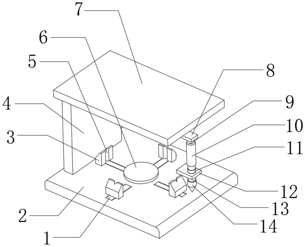
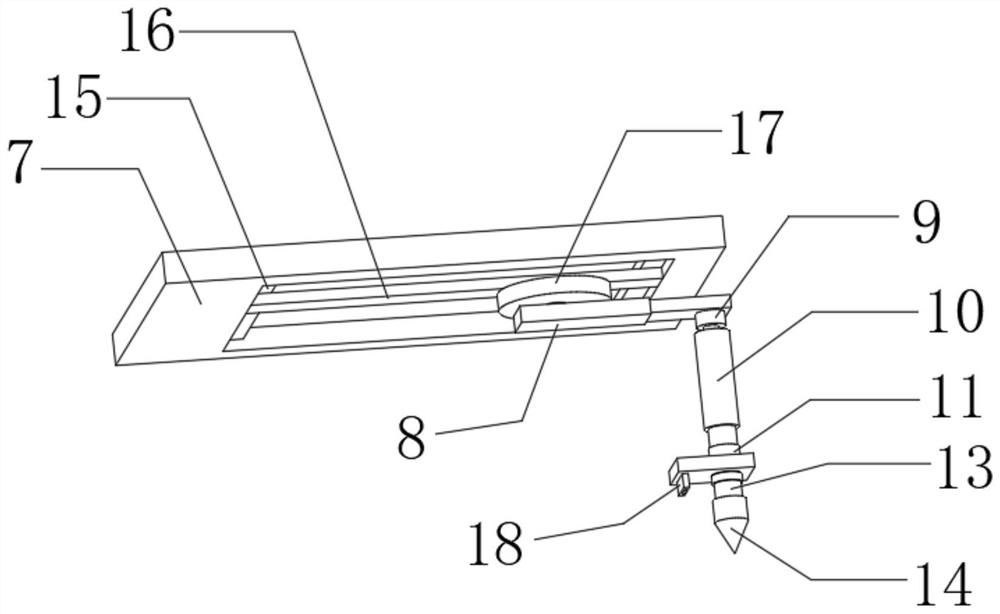
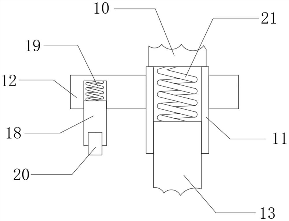
[0027] Reference Figure 1-4 , A chamfering device for circuit board production, comprising a supporting base 2. The outer wall on the top side of the supporting base 2 is connected with a first supporting plate 4 by bolts, and the top outer wall of the first supporting plate 4 is connected with a supporting top plate 7 by bolts , The bottom outer wall of the support top plate 7 is provided with a first groove, and the inner walls on both sides of the top of the first groove are connected with a second electric guide rail 15 through bolts, and the bottom outer walls of the two second electric guide rails 15 are slidably connected with a second Electric slider, and the bottom outer walls of the two second electric sliders are connected by bolts to the same third electric rail 16, and the bottom outer wall of the third electric rail 16 is slidably connected with the third electric slider. The bottom outer wall is connected with a mounting plate 17 through bolts, ...

Example Embodiment

[0035] Example 2

[0036] Reference Figure 1-5 , A chamfering device for circuit board production, further comprising an air duct 25 whose casing bolts are installed on one side of the outer wall of the first support plate 4, and one side of the outer wall of the air duct 25 is bolted to an air pump 24, and one end of the air duct 25 The outer wall of the air guide tube 26 is connected with an air guide tube 26 by bolts, and the outer wall of one end of the air guide tube 26 is connected with a jet head 27 by bolts, and the other end of the inner wall of the air guide tube 25 is connected with a filter screen 23 by bolts.

[0037] Working principle: After the device is used, the air guide tube 25, the air hose 26, the jet head 27 and the air pump 24 can be set to blow air from the air pump to the jet head. This improves the convenience of device cleaning.


PUM


Abstract

The invention belongs to the technical field of circuit board production, particularly relates to a chamfering device for circuit board production, and provides the following scheme for solving the problem that an existing chamfering device is poor in plate fixing stability. The scheme is that the chamfering device comprises a supporting base, and a first supporting plate is fixedly mounted on theouter wall of one side of the top of the supporting base; a supporting top plate is fixedly mounted on the outer wall of the top of the first supporting plate, a first groove is formed in the outer wall of the bottom of the supporting top plate, second electric guide rails are fixedly mounted on the inner walls of the two sides of the top of the first groove, and second electric sliding blocks are slidably connected to the outer walls of the bottoms of the two second electric guide rails. According to the invention, a second supporting plate, a first spring, a pressing plate and a rolling wheel are arranged, so in the chamfering operation process, the pressing plate and the rolling wheel can press the chamfering position of a plate, thereby further guaranteeing the chamfering stability, reducing friction through the rolling wheel, facilitating the movement of the device, and improving the chamfering smoothness.

Description

Technical field [0001] The invention relates to the technical field of circuit board production, in particular to a chamfering device for circuit board production. Background technique [0002] According to the number of layers, circuit boards are divided into three major categories: single-sided, double-sided and multi-layer circuit boards. They have the characteristics of high wiring density, light weight, thin thickness, and good flexibility. With the development of society , The manufacturing industry is becoming more and more automated, and most of the existing circuit board chamfering mechanisms on the market are grinding wheel cutting and chamfering. [0003] When the existing chamfering device chamfers the circuit board, the plate is clamped and fixed and then the chamfering operation is performed. When fixing the plate of different thickness, the plate cannot be protruded from the clamp. This further affects the chamfering operation and the stability of the chamfering. Th...

Claims


Application Information

Patent Timeline
IPC IPC(8): H05K3/00
CPCH05K3/0008H05K3/0044H05K3/0055
Inventor 刘财英
Owner 刘财英
Why Eureka
Try Eureka