
Transmission fault detection device used between communication system nodes

A fault detection and communication system technology, applied in transmission systems, digital transmission systems, electrical components, etc., can solve problems such as signal transmission faults, potential safety hazards, and inconvenient detection, so as to improve safety and convenience, save manpower, and improve convenience. The effect of stability and stability

Inactive Publication Date: 2021-08-27
佛山派乔星智能设备有限公司
View PDF0 Cites 0 Cited by
  • Summary
  • Abstract
  • Description
  • Claims
  • Application Information

AI Technical Summary

Problems solved by technology

[0002] The communication processing system used in the corresponding security monitoring field needs to be used with at least two or more signal processing and transmission nodes, but due to device aging and external environmental factors, there will be a problem of signal transmission failure. The current solution to this problem The method is to use at least two people to disassemble the two ends of the optical cable at two adjacent nodes, and use the laser to irradiate the optical cable to check one by one. During this period, personnel need to use their eyes to observe whether the laser is emitted from the inner cavity of the optical cable, which has certain potential safety hazards.
[0003] Aiming at the deficiencies of the prior art, the present invention provides a transmission fault detection device used between nodes of a communication system, which has the advantages of effectively improving the safety and convenience of detection and saving corresponding manpower, and solves the problem of common problems in communication. During the transmission fault detection process between system nodes, the detection is not convenient enough and requires two or more personnel to cooperate with the detection problem

Method used


Image

  • Transmission fault detection device used between communication system nodes
  • Transmission fault detection device used between communication system nodes
  • Transmission fault detection device used between communication system nodes

Examples


Embodiment Construction

[0020] The following will clearly and completely describe the technical solutions in the embodiments of the present invention with reference to the accompanying drawings in the embodiments of the present invention. Obviously, the described embodiments are only some, not all, embodiments of the present invention. Based on the embodiments of the present invention, all other embodiments obtained by persons of ordinary skill in the art without making creative efforts belong to the protection scope of the present invention.

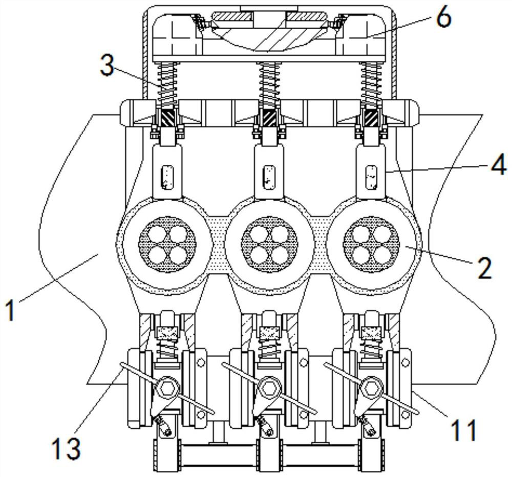
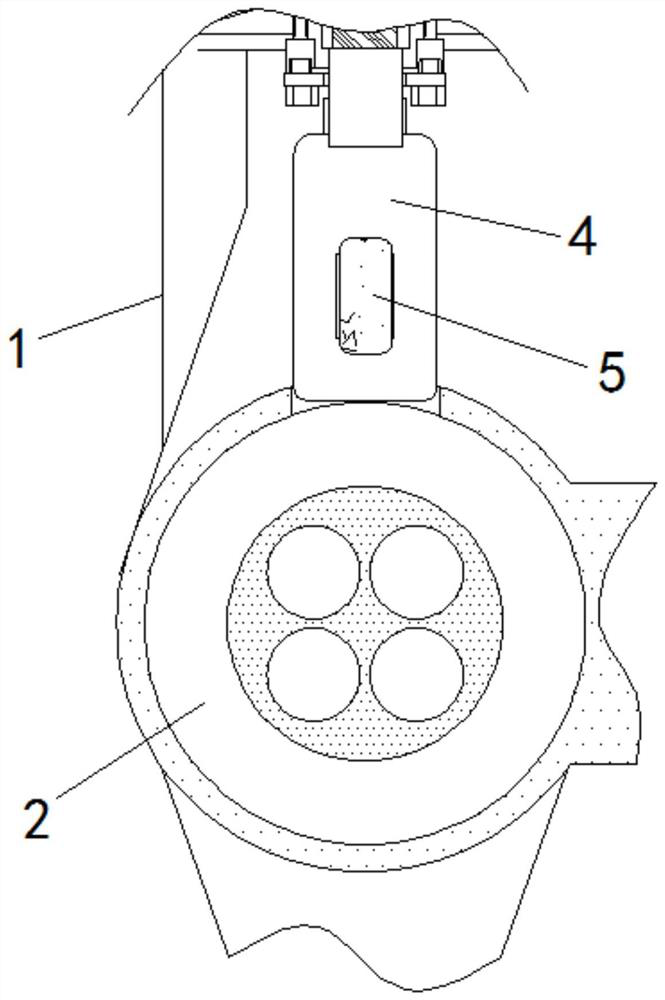
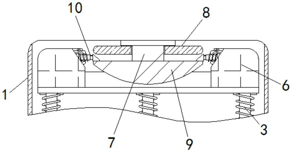
[0021] see Figure 1-4 , a transmission fault detection device for communication system nodes, including a base 1, the middle part of the base 1 is uniformly provided with a plug-in tube 2, the surface of the base 1 is slidably plugged with an elastic column 3 above the plug-in tube 2, and the elastic column 3 The lower end of the elastic column 3 is fixedly connected with a shielding plate 4 extending into the wall cavity of the socket tube 2, the surface of ...


PUM


Abstract

The invention relates to the technical field of communication processing systems, and discloses a transmission fault detection device used between communication system nodes, which comprises a base. The middle of the base is uniformly provided with insertion pipes, and elastic columns are slidably inserted above the insertion pipes on the surface of the base, and the lower end of the elastic column is fixedly connected with a shielding plate extending into the wall cavity of the insertion pipe, the surface of the shielding plate is fixedly connected with a photoresistor, and the upper end of the elastic column is fixedly connected with a clamping block. According to the transmission fault detection device used between the communication system nodes, a clamping block is lifted to enable a telescopic wedge column to cross an adjusting ring, after the clamping block is loosened, the telescopic wedge column is not limited by a bowl-shaped block, a shielding plate is driven to be inserted into an inner cavity of an insertion pipe, then laser is irradiated into an optical cable in a matched mode, and a fault is judged according to state conversion of a rotating handle. Therefore, the safety and convenience of detection are effectively improved, and corresponding manpower is saved.

Description

technical field [0001] The invention relates to the technical field of communication processing systems, in particular to a transmission fault detection device used between communication system nodes. Background technique [0002] The communication processing system used in the corresponding security monitoring field needs to be used with at least two or more signal processing and transmission nodes, but due to device aging and external environmental factors, there will be a problem of signal transmission failure. The current solution to this problem The method is to use at least two people to disassemble the two ends of the optical cable at two adjacent nodes, and use the laser to irradiate the optical cable to check one by one. During this period, personnel need to use their eyes to observe whether the laser is emitted from the inner cavity of the optical cable, which has certain potential safety hazards. . [0003] Aiming at the deficiencies of the prior art, the present...

Claims


Application Information

Patent Timeline
IPC IPC(8): H04L12/26H04L12/24
CPCH04L41/06H04L43/0823H04L43/50
Inventor 向华晖
Owner 佛山派乔星智能设备有限公司
Learn More