Rope type vascular anastomosis device

A rope and blood vessel technology, which is applied in the field of rope-type vascular anastomosis device, can solve the problems of quality control affected by doctor's technology, long anhepatic period, and difficulty in keeping it long, so as to increase convenience and stability, reduce failure rate, and speed up The effect of reconstruction speed

Pending Publication Date: 2022-01-25
华融科创生物科技(天津)有限公司
View PDF0 Cites 0 Cited by
  • Summary
  • Abstract
  • Description
  • Claims
  • Application Information

AI Technical Summary

Problems solved by technology

For example, the receptors of the superior and inferior hepatic vena cava are difficult to lengthen and are easy to retract, and the diameter of the blood vessels ranges from 10 to 30 mm, which cannot be achieved with existing instruments
At present, the common method in the world is still manual continuous valgus suturing. Due to the narrow space, the operation is difficult, time-consuming and laborious. The average vascular reconstruction takes 35-60 minutes, resulting in a long anhepatic period during the operation, which has a great impact on the heart, lungs and other organs. Quality control is affected by doctors' skills, and complications such as postoperative bleeding and vascular interface stenosis are prone to occur, which is the most critical part of organ transplantation

Method used


Image

  • Rope type vascular anastomosis device
  • Rope type vascular anastomosis device
  • Rope type vascular anastomosis device

Examples


Embodiment 1

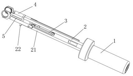
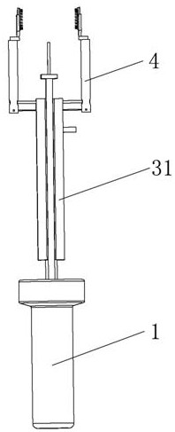
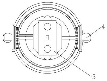
[0041] The rope-type vascular anastomosis device includes an operating handle 1, a connecting structure 2, a pulling device 3 and an anastomotic device 4. The operating handle 1 is fixed with a connecting structure 2, and the connecting structure 2 is slidably provided with a pulling device 3. The anastomotic device 4 is connected with the pulling device 4. The device 3 is movably connected, the pulling device 3 is provided with a connecting rod 33, the anastomotic device 4 is movably connected and arranged on both sides of the connecting rod 33, the anastomotic device 4 is connected with the pulling structure in the pulling device 3 through a rope, and the pulling structure is passed through the pulling rod 32 is connected with the driving structure in the handle 1.

[0042] The pulling device 3 comprises a grip handle 31, a pull bar 32, a connecting rod 33, a reversing plate 34, a fixed pulley 35 and a trigger 36. The grip handle 31 is slidably arranged on the connection stru...

Embodiment 2

[0052] On the basis of Embodiment 1, the base 42 is provided with an insertion pile 423, and the insertion pile 423 is provided with an assembly groove 424, a reversing groove 425 and a positioning groove 426, and the assembly groove 424 is a linear groove on the outer wall axis of the insertion pile 423, The reversing groove 425 is an annular groove, and the positioning groove 426 is arranged in an annular array on the outer wall of the insertion pile 423 . The assembly groove 424 , the reversing groove 425 and the positioning groove 426 communicate with each other.

[0053] The sleeve 43 is provided with a connection cavity 431, which is connected to the insertion pile 423 through a threaded structure. The connection cavity 431 is provided with an elastic member and a positioning pin 432, and the positioning pin 432 is respectively connected to the assembly groove 424 and the reversing pin. The groove 425 matches the positioning groove 426 .

[0054] like Figure 13-17 As s...

Embodiment 3

[0056] On the basis of Embodiment 1, the base 42 is provided with an insertion pile 423, and the insertion pile 423 is connected with the connecting cavity 431 provided on the sleeve 43 through threads, and the base 42 is provided with a first stopper 427, The first limiting block 427 is matched with the second limiting block 433 provided on the sleeve 43 , and an elastic member is arranged in the connecting cavity 431 .

[0057] In order to facilitate the operation of turning the blood vessel through the anastomotic ring 41 and then hanging the needle, the limit structure of the base 42 and the sleeve 43 is improved. like Figure 18-21 As shown, the position is limited by setting the first limit block 427 and the second limit block 433 on the base 42 and the sleeve 43 respectively. After rotating to the specified position, the two limit blocks perform mutual limit to realize the function, and an elastic member is provided in the connecting cavity 431 to make the operation mo...


PUM


Abstract

A rope type blood vessel anastomosis device comprises an operating handle, a connecting structure, a pulling device and anastomosis devices, the connecting structure is fixedly arranged on the operating handle, the pulling device is arranged on the connecting structure in a sliding mode, the anastomosis devices are movably connected with the pulling device, a connecting rod is arranged on the pulling device, the anastomosis devices are movably connected to the two sides of the connecting rod, the anastomosis device is connected with a pulling structure in the pulling device through a rope, and the pulling structure is connected with a driving structure in the operating handle through a pulling rod. The anastomosis device has the beneficial effect that the anastomosis can be stopped after the anastomosis degree of the anastomosis ring is determined. The problem that the final anastomosis state, namely the distance between the two anastomosis rings, is different due to different wall thicknesses of blood vessels even if the diameters of the blood vessels are the same in actual operation is solved. On the basis, the structures of the base and the sleeve of the anastomosis part are further improved, so that the blood vessel can be conveniently turned outwards to hang the needle after penetrating through the anastomosis ring.

Description

technical field [0001] The invention relates to the field of medical instruments, and more specifically relates to a rope type blood vessel anastomosis device. Background technique [0002] Organ transplantation is a complex procedure in which a healthy organ is transplanted into a patient's body to replace a patient's non-functional organ due to disease. With the continuous improvement of organ transplantation techniques and surgical treatment levels, the survival rate and quality of life of organ transplant patients have been significantly improved. Organ transplantation technology has become an effective means of treating various end-stage organ diseases. [0003] In liver and kidney transplantation, the most difficult and technically demanding part of new organ implantation after organ resection is the repair and reconstruction of the arteriovenous vessels on the donor viscera, which has decisive significance for the success rate of the operation and postoperative recove...

Claims


Application Information

Patent Timeline
IPC IPC(8): A61B17/11
CPCA61B17/11A61B2017/1107A61B2017/1132
Inventor 刘文斌刘德鹏
Owner 华融科创生物科技(天津)有限公司
Why Eureka
Try Eureka