Medical postoperative patient transfer device

A transfer device and medical technology, which is applied in medical transportation, hospital beds, medical science, etc. It can solve the problem that at least two medical staff need to work together to lift a patient, which is very inconvenient, the workload of medical staff is heavy, and the patient is injured again. problem, achieve the effect of preventing slipping, reducing labor intensity and preventing secondary injury

Active Publication Date: 2020-11-13
安徽诺多康医疗科技有限公司
View PDF14 Cites 6 Cited by
  • Summary
  • Abstract
  • Description
  • Claims
  • Application Information

AI Technical Summary

Problems solved by technology

[0002] After the patient has completed the operation, it is necessary to transfer the postoperative patient from the operating table to the bed in the ward. At present, the medical staff uses a cart to transfer the postoperative patient. When transferring the postoperative patient, the medical staff first needs to manually The postoperative patient is lifted from the operating table and placed on the trolley, and then the postoperative patient is lifted from the trolley and placed on the bed in the ward. This requires the medical staff to repeatedly lift the postoperative patient, so that the medical staff The workload is large, and the labor intensity is also high; and lifting the patient requires at least two medical staff to work together, which is very inconvenient, and the medical staff manually repeatedly lifts the postoperative patient in the process, which may easily lead to secondary injuries of the postoperative patient , easily lead to wound dehiscence

Method used


Image

  • Medical postoperative patient transfer device
  • Medical postoperative patient transfer device
  • Medical postoperative patient transfer device

Examples


Embodiment 1

[0024] A postoperative patient transfer device for medical use, such as Figure 1-3 As shown, it includes a base 1, a walking wheel 2, a sliding seat 3, a handle frame 4, a lifting mechanism 5, and a human body support assembly 6. Side is connected with slide seat 3, and slide seat 3 right side upper part is connected with handle frame 4, and elevating mechanism 5 is installed between base 1 and slide seat 3, and human body supporting assembly 6 is installed on elevating mechanism 5.

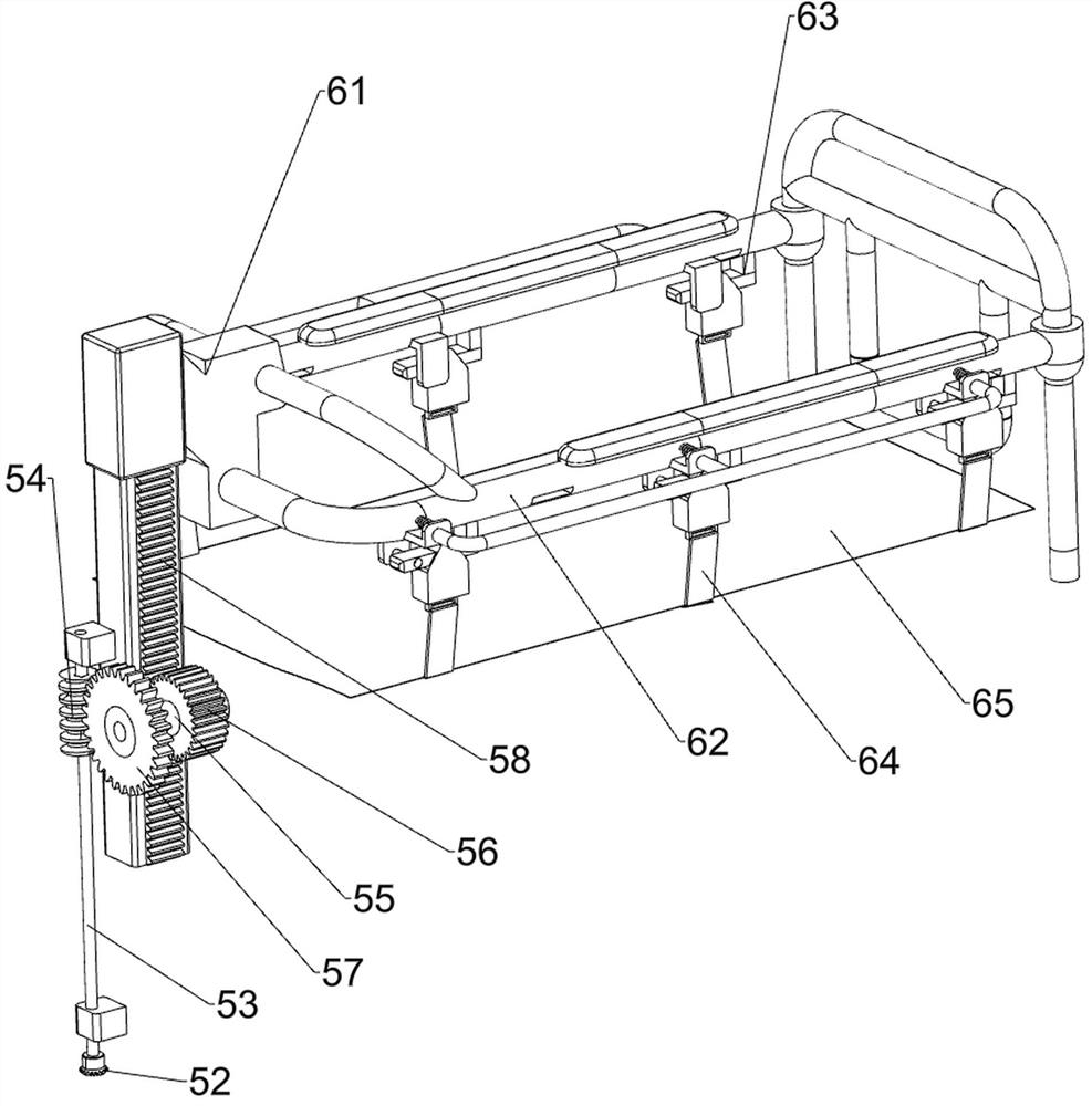
[0025] The lifting mechanism 5 includes a reduction motor 51, a bevel gear transmission group 52, a transmission shaft 53, a worm screw 54, a rotating shaft 55, a cylindrical gear 56, a worm wheel 57 and a rack 58, and the top of the base 1 on the right side of the slide seat 3 is equipped with a reduction motor 51 The right side of the sliding seat 3 on the lower side of the handle frame 4 is rotatably connected with a transmission shaft 53, the bottom end of the transmission shaft 53 and the o...

Embodiment 2

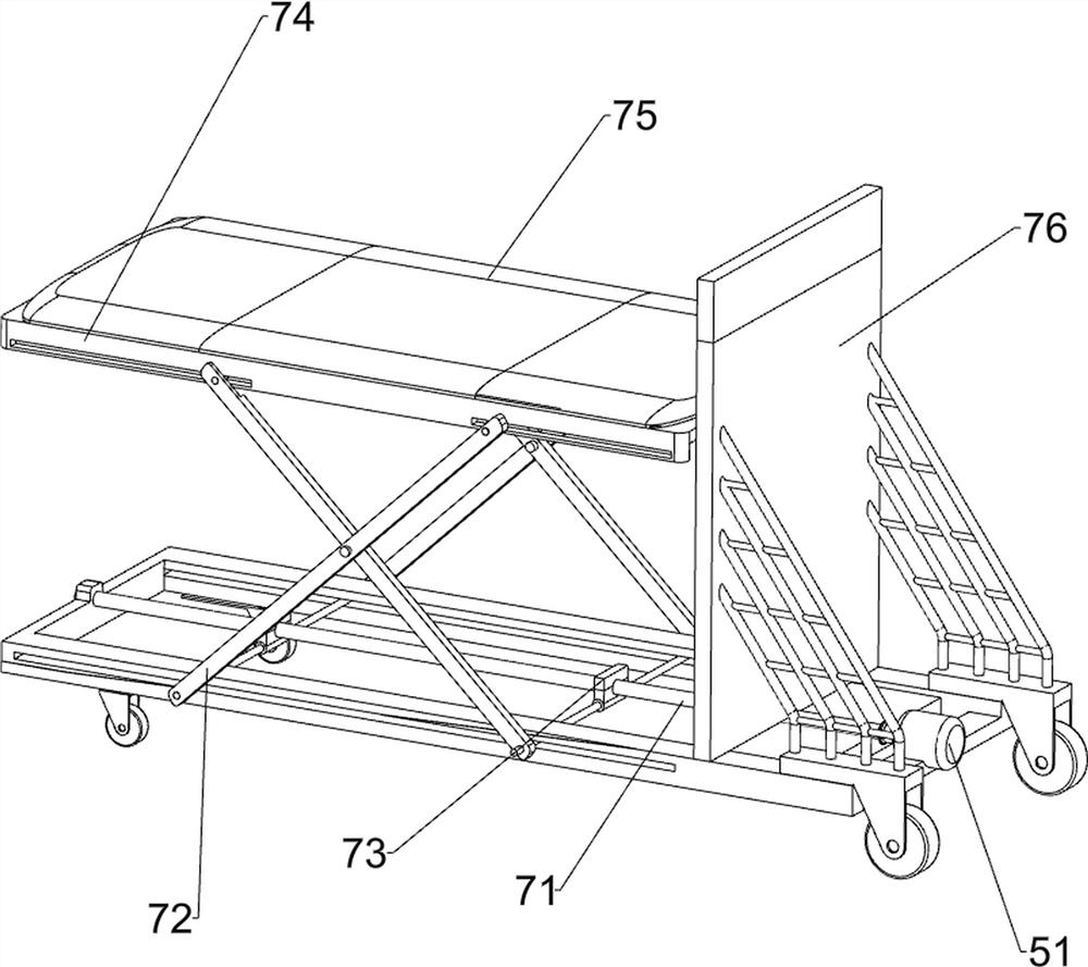
[0029] On the basis of Example 1, such as image 3 As shown, a support mechanism 7 is also included, and the support mechanism 7 includes a two-way screw rod 71, an X-shaped folding frame 72, a nut 73, a support bed board 74, a cushion 75 and a riser 76, and the output shaft of the reduction motor 51 passes through a coupling A two-way screw 71 is connected, and the two-way screw 71 is rotationally connected with the base 1. The left and right sides of the two-way screw 71 are connected with nuts 73 through screw connections, and an X-shaped folding frame 72 is rotatably connected between the two nuts 73. , the X-shaped folding frame 72 is slidingly connected with the base 1, the base 1 on the left side of the sliding seat 3 is connected with a riser 76, the riser 76 is connected with the two-way screw 71 in a rotational manner, and the left side of the riser 76 is slidably connected with a support The bed board 74 is slidably connected with the X-shaped folding frame 72, and ...

Embodiment 3

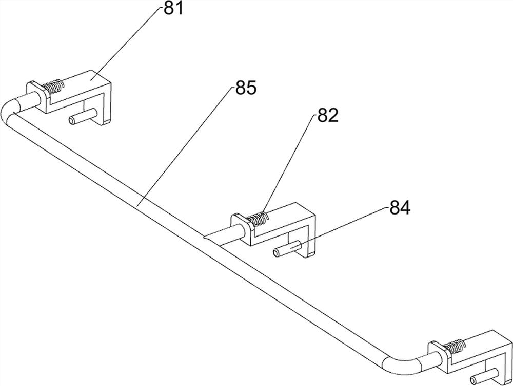
[0031] On the basis of Example 2, such as Figure 4-5 As shown, the safety assembly 8 is also included, and the safety assembly 8 includes a Z-shaped plate 81, a tension spring 82, a safety pin 84 and a connecting rod 85, and the front and rear sides of the support bracket 62 are slidingly connected with a plurality of Z Type plate 81, Z-shaped plate 81 and support bracket 62 are connected with extension spring 82, have safety hole 83 on the hook 63, safety pin 84 is slidably connected in safety hole 83, safety pin 84 and Z word The inner surfaces of the shaped plates 81 are connected, and connecting rods 85 are connected between the outer surfaces of the plurality of Z-shaped plates 81 .

[0032] The safety pin 84 can be positioned in the safety hole 83 by the extension spring 82, and the sling 64 can be fixed on the hook 63 by the safety pin 84, so as to prevent the sling 64 from slipping off the hook 63 during the movement of the device, thereby preventing the postoperative p...


PUM


Abstract

The invention relates to a transfer device, in particular to a medical postoperative patient transfer device. According to the medical postoperative patient transfer device, a postoperative patient can be conveniently transferred to a sickbed of a ward from an operating table, and a medical worker does not need to lift the patient manually and repeatedly. The medical postoperative patient transferdevice comprises a base, a sliding seat, a handle frame, a lifting mechanism, and a human body supporting assembly. A plurality of walking wheels are rotatably connected to the bottom of the base; the top of the base is connected with the sliding seat; one side of the sliding seat is connected with the handle frame; the lifting mechanism is mounted between the base and the sliding seat; and the human body supporting assembly is mounted on the lifting mechanism. Through mutual cooperation of the lifting mechanism and the human body supporting assembly, a postoperative patient can be conveniently transferred to a sickbed of a ward from an operating table, a medical worker does not need to manually and repeatedly lift the patient to transfer the patient to the sickbed, so that secondary injury to the patient can be prevented.

Description

technical field [0001] The invention relates to a transfer device, in particular to a transfer device for postoperative patients used in medical treatment. Background technique [0002] After the patient has completed the operation, it is necessary to transfer the postoperative patient from the operating table to the bed in the ward. At present, the medical staff uses a cart to transfer the postoperative patient. When transferring the postoperative patient, the medical staff first needs to manually The postoperative patient is lifted from the operating table and placed on the trolley, and then the postoperative patient is lifted from the trolley and placed on the bed in the ward. This requires the medical staff to repeatedly lift the postoperative patient, so that the medical staff The workload is large, and the labor intensity is also high; and lifting the patient requires at least two medical staff to work together, which is very inconvenient, and the medical staff manuall...

Claims


Application Information

Patent Timeline
Patent Type & Authority Applications(China)
IPC IPC(8): A61G1/02A61G1/04A61G1/048A61G7/10A61G7/14
CPCA61G1/02A61G1/04A61G1/048A61G7/1013A61G7/1025
Inventor 王考芳
Owner 安徽诺多康医疗科技有限公司
Why Eureka
Try Eureka