
Oil collector for realizing petroleum separation in petrochemical engineering

A petrochemical and oil collector technology, applied in the field of oil collectors, can solve the problems of polluting the environment, wasting oil resources, poor oil fluidity, etc.

Active Publication Date: 2020-11-13
盐城市冉峰机械设备制造有限公司
View PDF3 Cites 1 Cited by
  • Summary
  • Abstract
  • Description
  • Claims
  • Application Information

AI Technical Summary

Problems solved by technology

[0003] The purpose of the present invention is to provide a kind of oil collector that realizes oil separation in petrochemical industry, in order to solve the problem that due to the poor fluidity of oil, there will be a small amount of oil attached to the inner wall of the oil collector outlet. After separation, there will be oil dripping, which not only pollutes the environment but also wastes oil resources.

Method used


Image

  • Oil collector for realizing petroleum separation in petrochemical engineering
  • Oil collector for realizing petroleum separation in petrochemical engineering
  • Oil collector for realizing petroleum separation in petrochemical engineering

Examples


Embodiment 1

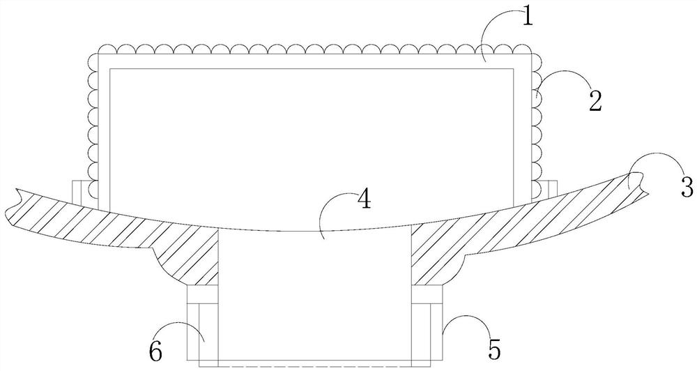
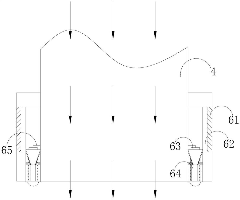
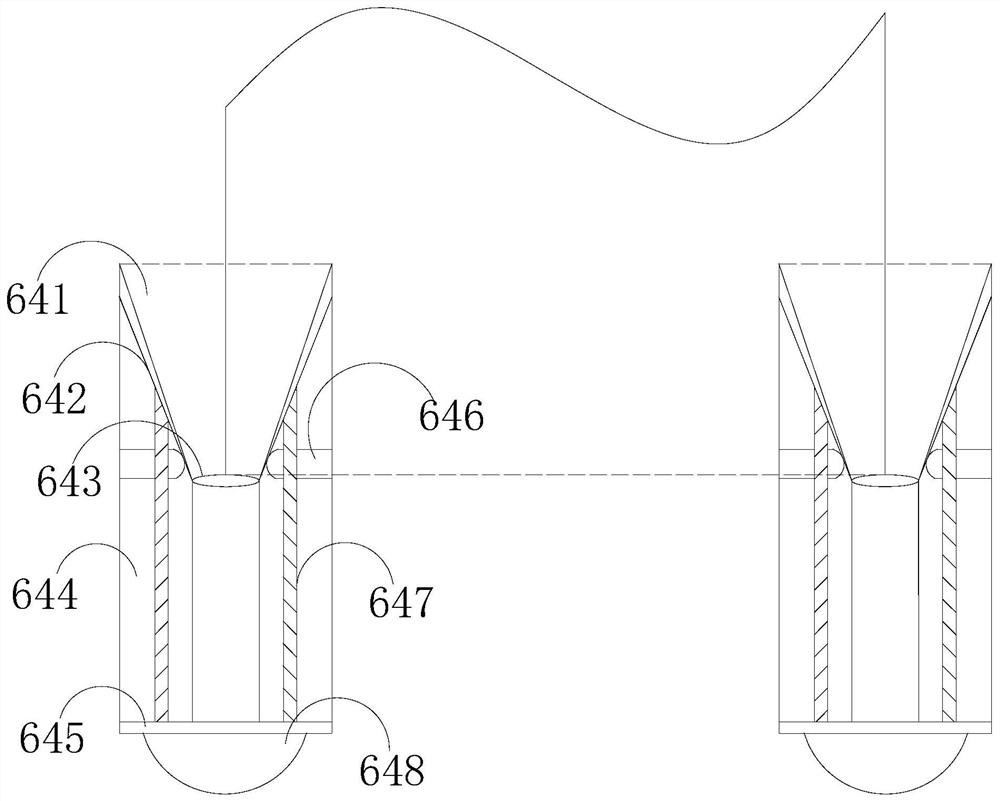
[0022] like Figure 1-Figure 5 As shown, the present invention provides an oil collector for realizing oil separation in petrochemical industry. Its structure includes an oil collection tank 1, a damping ball 2, a base 3, an oil collection joint 4, a pipe sleeve 5, and a liquid leakage collector 6. The outer surface of the oil collection tank 1 is provided with shock-absorbing balls 2, the oil collection tank 1 and the base 3 are welded together, the oil collection joint 4 communicates with the oil collection tank 1, and the oil collection joint 4 is nested in the sleeve 5, a leakage collector 6 is provided between the pipe sleeve 5 and the oil collection joint 4, and the leakage collector 6 includes a spacer 61, a lifting cylinder 62, a running wheel 63, a recovery device 64, and a suspension cable 65. The lifting cylinder 62 is in contact with the spacer 61 , and the lifting cylinder 62 is mechanically connected with the recovery device 64 , and the recovery device 64 is pro...


PUM


Abstract

The invention discloses an oil collector for realizing petroleum separation in petrochemical engineering. The oil collector comprises an oil collecting tank, a damping ball, a base, an oil collectingconnecting pipe, a pipe sleeve and a leaked liquid collector, the damping ball is arranged on the outer surface of the oil collecting tank, the oil collecting tank and the base are welded together, the oil collecting connecting pipe is communicated with the oil collecting groove, the oil collecting connecting pipe is embedded in the pipe sleeve, a leaked liquid collector is arranged between the pipe sleeve and the oil collecting connecting pipe, according to the invention, the oil collecting cavity, the elastic sheet and the telescopic cylinder act synchronously, during petroleum collection, the elastic sheet is extruded by the outer surface of the oil collecting connecting pipe, petroleum collection completion, the telescopic cylinder drives the leaked liquid collector to vertically movedownwards along the surface of the oil collecting connecting pipe, under the condition of no external force extrusion of the oil collecting connecting pipe, the elastic piece is bounced off, then theoil collecting cavity closed by the elastic piece is opened, half of the elastic piece is exposed in the oil collecting connecting pipe, and the other half of the elastic piece is located outside theoil collecting connecting pipe, so that residual petroleum in the oil collecting connecting pipe is recycled through the oil collecting cavity, and the phenomenon of oil dripping is prevented.

Description

technical field [0001] The invention relates to the technical field of oil separation, in particular to an oil collector for realizing oil separation in petrochemical industry. Background technique [0002] With the development of socialist modernization in recent years, the demand for oil in various industries has been greatly strengthened, and the petrochemical industry has also developed rapidly. After oil separation, oil with a certain purity needs to be collected with an oil collector. When the pressure of the pressure gauge of the pressure gauge rises, it is necessary to drain the oil, open the oil drain valve, and transfer the oil to another container. During the oil drain, due to the poor fluidity of the oil, there will be a small amount of oil attached to the oil drain port of the oil collector. At the position of the inner mouth wall, when the oil outlet is separated, oil dripping will occur, and the oil dripping not only pollutes the environment but also wastes oi...

Claims


Application Information

Patent Timeline
Patent Type & Authority Applications(China)
IPC IPC(8): B01D17/032
CPCB01D17/0214
Inventor 赵晓琳
Owner 盐城市冉峰机械设备制造有限公司
Learn More