
Textile yarn oiling device

A textile thread and oil roller technology, applied in textiles and papermaking, filament/thread forming, fiber treatment, etc., can solve the problems of drying treatment, oil waste, excessive oil, etc., to prevent oil dripping and reduce dripping The effect of sprinkling amount and preventing waste

Inactive Publication Date: 2018-09-14
XIANGSHUI ZHONGXING TEXTILE CO LTD
View PDF0 Cites 9 Cited by
  • Summary
  • Abstract
  • Description
  • Claims
  • Application Information

AI Technical Summary

Problems solved by technology

[0003] The purpose of the present invention is to solve the problem in the prior art that there is more oil stained on the thread, which leads to the failure to achieve the expected texturizing effect, and also causes waste of oil. Affecting the oiling effect, the problem that the drying process cannot be carried out in time, and a kind of oiling device on the textile line is proposed

Method used

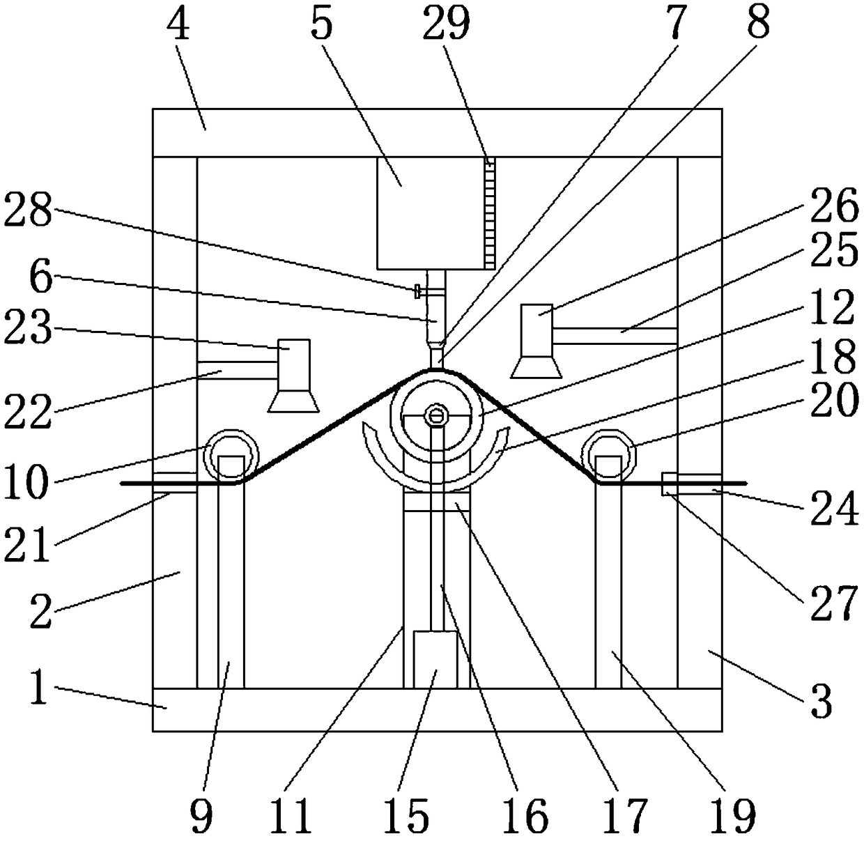

Image

  • Textile yarn oiling device
  • Textile yarn oiling device

Examples


Embodiment Construction

[0020] The following will clearly and completely describe the technical solutions in the embodiments of the present invention with reference to the accompanying drawings in the embodiments of the present invention. Obviously, the described embodiments are only some, not all, embodiments of the present invention.

[0021] In describing the present invention, it should be understood that the terms "upper", "lower", "front", "rear", "left", "right", "top", "bottom", "inner", " The orientation or positional relationship indicated by "outside", etc. is based on the orientation or positional relationship shown in the drawings, and is only for the convenience of describing the present invention and simplifying the description, rather than indicating or implying that the referred device or element must have a specific orientation, so as to Specific orientation configurations and operations, therefore, are not to be construed as limitations on the invention.

[0022] refer to Figure ...


PUM


Abstract

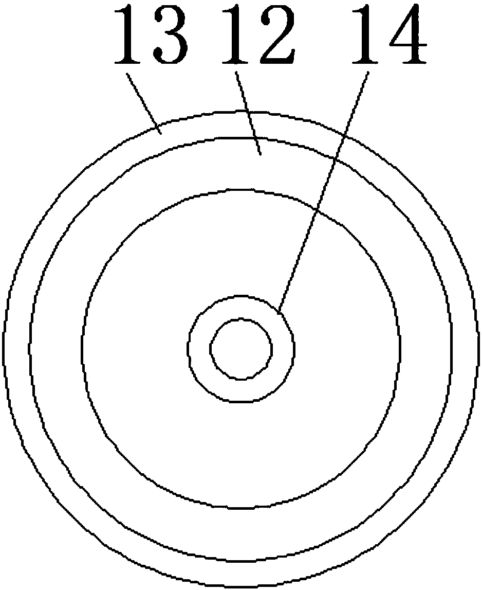
The invention discloses a textile yarn oiling device. The textile yarn oiling device comprises a base, a left supporting plate and a right supporting plate are arranged on the tops of the two sides ofthe base respectively, one top plate is arranged on the tops of the left supporting plate and right supporting plate, an oil storage tank is arranged at the bottom of the top plate, a connecting pipeis arranged at the bottom of the oil storage tank, an oil discharging nozzle is arranged at the bottom of the connecting pipe, a sponge is arranged at the bottom of the oil discharging nozzle, and asecond supporting rod is arranged on the top of the base; an oil rubbing roller is arranged on the top of the second supporting rod, a roller is arranged at the center of the oil rubbing roller, a motor is arranged at the bottom of an inner cavity of the second supporting rod, a connecting shaft is connected with the roller and arranged at an output end of the motor, a fixing plate is arranged onthe upper portion of the second supporting rod, and an oil saving groove is formed in the top of the fixing plate; a first connecting rod is arranged on one side of a left supporting plate, a dust suction machine is arranged at one end of the first connecting rod, a second connecting rod is arranged on one side of a right supporting plate, and a dryer is arranged at one end of the second connecting rod. According to the textile yarn oiling device, waste of oil materials can be effectively reduced, and textile yarn after oiling can be quickly dried.

Description

technical field [0001] The invention relates to the technical field of textiles, in particular to a textile thread oiling device. Background technique [0002] In textile production, when changing non-elastic or low-elastic textile threads into high-elastic ones, it is necessary to oil the textile threads. After oiling, the toughness of the textile threads becomes stronger, which is conducive to subsequent elastication. operate. The general textile thread oiling device is to soak the silk thread in the oil, which will cause more oil to be contaminated on the thread, resulting in the failure to achieve the expected texturizing effect and waste of oil. The previous oiling There is a lot of dust in the device, which will affect the oiling effect and cannot be dried in time. Contents of the invention [0003] The purpose of the present invention is to solve the problem in the prior art that there is more oil stained on the thread, which leads to the failure to achieve the ex...

Claims


Application Information

Patent Timeline
IPC IPC(8): D01D5/096D01D10/06
CPCD01D5/096D01D10/06
Inventor 袁以权
Owner XIANGSHUI ZHONGXING TEXTILE CO LTD
Learn More