Wood strip grinding machine for wood processing
A technology for grinding machines and wood strips, which is applied in the direction of grinding frames, metal processing equipment, grinding machine parts, etc., can solve the problems of time-consuming and laborious, and achieve the effect of improving work efficiency
- Summary
- Abstract
- Description
- Claims
- Application Information
AI Technical Summary
Problems solved by technology
Method used
Image
Examples
Embodiment 1
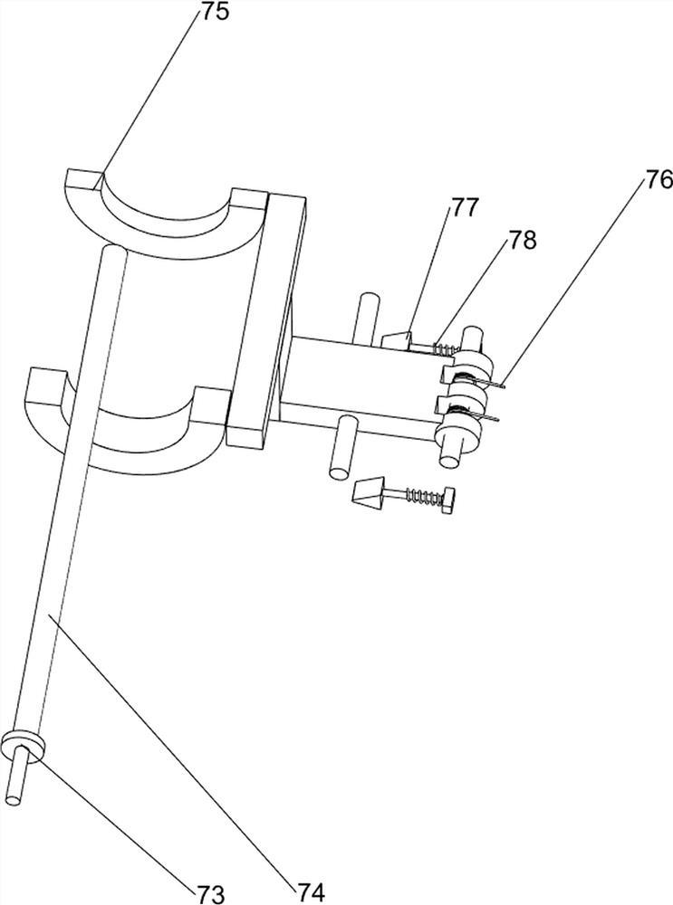
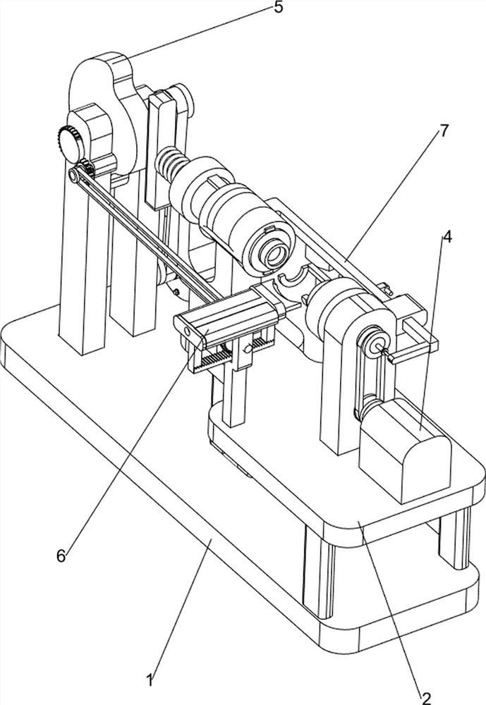
[0059] A wood strip sander for wood processing, such as Figure 1-3 As shown, it includes a base 1, a working frame 2, a geared motor 3, a rotating mechanism 4, a propulsion mechanism 5, and a cutting mechanism 6. The right side of the base 1 is provided with a working frame 2, and the rear part of the left side of the base 1 is connected to a geared motor 3. The right side of the top of the work frame 2 is provided with a rotating mechanism 4 , a propulsion mechanism 5 is connected between the left side of the base 1 and the output shaft of the geared motor 3 , and a cutting mechanism 6 is connected between the propulsion mechanism 5 and the front of the base 1 .
[0060]When people need to polish the wooden strips, the wooden strips are first placed on the parts of the rotating mechanism 4, and then the reduction motor 3 is started. The rotation of the output shaft of the reduction motor 3 drives the propulsion mechanism 5 to rotate, so that the wooden strips are fixed, and t...
Embodiment 2
[0062] On the basis of Example 1, such as Figure 4-5 As shown, the rotating mechanism 4 includes a transmission motor 41, a first belt set 42, a first rotating shaft 43 and a motor squeeze switch 44, the right side of the top of the work frame 2 is provided with a transmission motor 41, and the top middle of the work frame 2 is connected in a rotating manner. The first rotating shaft 43 is arranged, and the first belt set 42 is connected between the first rotating shaft 43 right-hand end and the transmission motor 41 output shaft, and the top rear side of the work frame 2 is provided with a motor extrusion switch 44.
[0063] When people need to polish the wooden strips, the wooden strips are first placed on the first rotating shaft 43, and under the cooperation of the propulsion mechanism 5 and the cutting mechanism 6, the motor squeeze switch 44 is started, and the output shaft of the transmission motor 41 rotates to drive the first rotating shaft. The belt set 42 and the f...
Embodiment 3
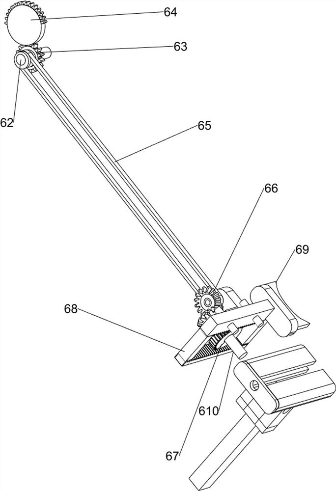
[0067] On the basis of Example 2, such as Figure 6-9 As shown, the cutting mechanism 6 includes a first support frame 61, a third transmission shaft 62, a full gear 63, a first half gear 64, a third belt set 65, a bevel gear assembly 66, a second half gear 67, a rack frame 68. Grinding the blade 69 and the connecting shaft 610, the left front side of the working frame 2 is connected with the first support frame 61, the front end of the first transmission shaft 52 is connected with the first half gear 64, and the upper left side of the base 1 is connected with the third Transmission shaft 62, the middle part of the third transmission shaft 62 is connected with the full gear 63, the full gear 63 meshes with the first half gear 64, the connecting shaft 610 is connected in rotation between the top of the first support frame 61, and the middle part of the connecting shaft 610 is connected with the second Two half gears 67, a rack frame 68 is slidably connected to the top of the fi...
PUM
 Abstract
Description
Claims
Application Information
 - R&D
- Intellectual Property
- Life Sciences
- Materials
- Tech Scout
- Unparalleled Data Quality
- Higher Quality Content
- 60% Fewer Hallucinations
Browse by: Latest US Patents, China's latest patents, Technical Efficacy Thesaurus, Application Domain, Technology Topic, Popular Technical Reports.
© 2025 PatSnap. All rights reserved.Legal|Privacy policy|Modern Slavery Act Transparency Statement|Sitemap|About US| Contact US: help@patsnap.com


