Building material drying device

A technology for drying devices and building materials, which is applied in drying, drying machines, heating devices, etc., and can solve the problems of limited moving range of stirring rods, single stirring form, and building materials that cannot be directly stirred by stirring rods.

Active Publication Date: 2020-08-28
CHONGQING VOCATIONAL INST OF ENG
View PDF6 Cites 8 Cited by
  • Summary
  • Abstract
  • Description
  • Claims
  • Application Information

AI Technical Summary

Problems solved by technology

[0004] However, the stirring shaft can only rotate in a circle, and the stirring shaft can only stir the building materials in the circumferential direction, and cannot move in other directions, so that the stirring form of the stirring shaft to the building materials is relatively simple, so the movement of the stirring rod on the stirring shaft The range is limited, and some building materials cannot be directly stirred by the stirring rods (such as building materials between adjacent stirring rods), so the drying effect of the drying cylinder needs to be further improved

Method used


Image

  • Building material drying device
  • Building material drying device
  • Building material drying device

Examples


Embodiment 1

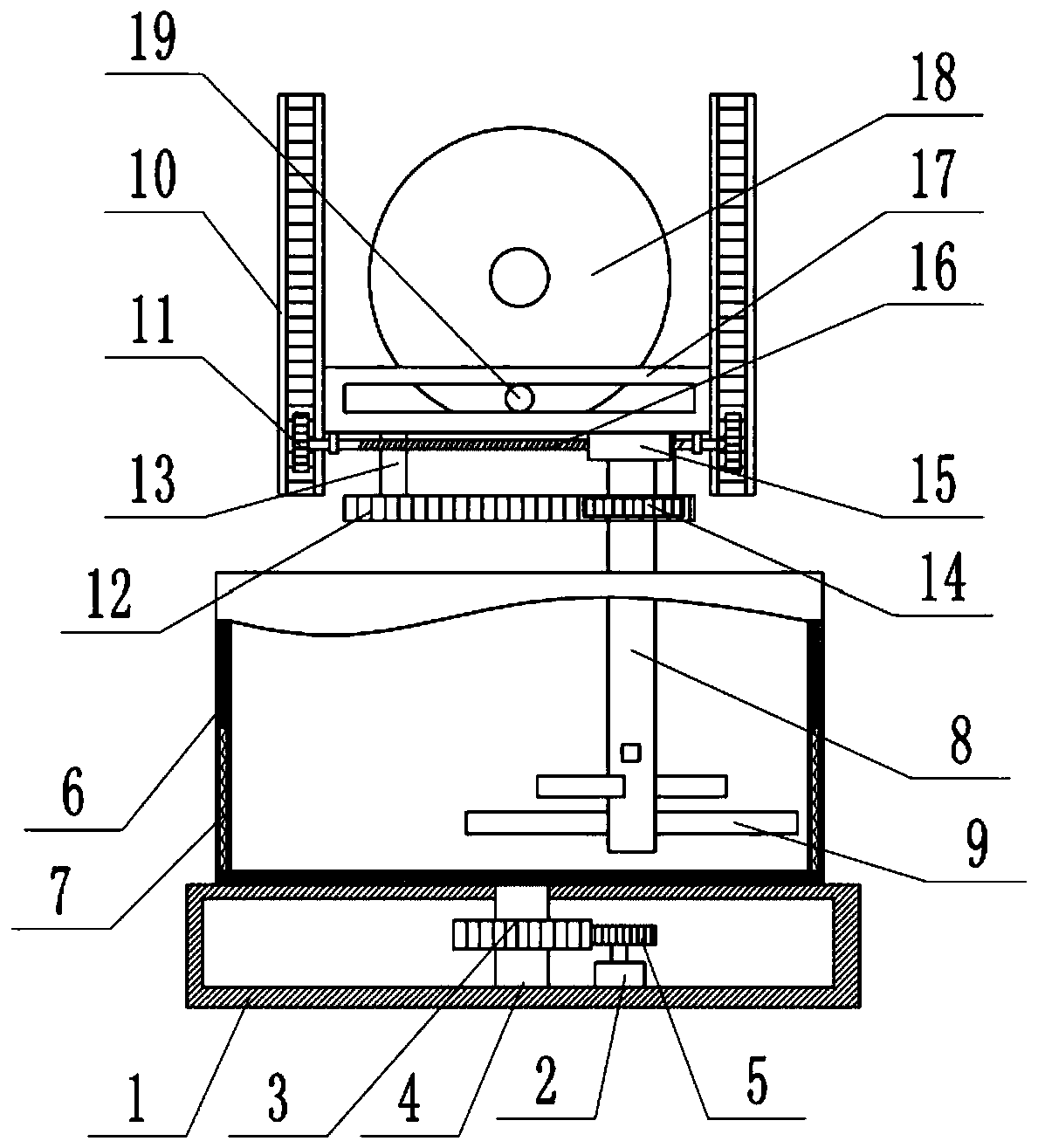
[0026] Basic as attached Figure 1-Figure 2 Shown: a drying device for building materials, including a frame, a base 1, a drying cylinder 6 with heating function, a stirring shaft 8 and a stirring rod 9, combined with figure 2 As shown, the stirring rods 9 are welded on the stirring shaft 8 , and the projections of the stirring rods 9 in the axial direction of the stirring shaft 8 are distributed in a staggered manner. The drying cylinder 6 is located on the base 1, and the drying cylinder 6 is rotatably connected to the base 1. Specifically, the bottom of the base 1 is provided with a drive chamber, and the motor 2 is fixed in the drive chamber by screws, and the output shaft of the motor 2 is passed through a flat The key is coaxially fixed with a driving gear 5, and the bottom of the base 1 is connected with a drive shaft 4 through bearing rotation, the top of the drive shaft 4 passes through the top of the base 1 and is welded to the bottom of the drying cylinder 6, and t...

Embodiment 2

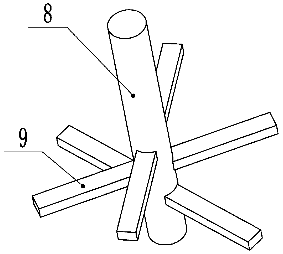
[0038] combine Image 6 As shown, the stirring rod 9 in the present embodiment is provided with several material holes 25, the material holes 25 vertically penetrate the stirring rod 9, the material holes 25 are stepped holes, and the diameter of the bottom end of the material hole 25 is greater than the diameter of the material hole 25 tops , the bottom of the feed hole 25 is provided with a baffle plate 27 hinged on the stirring rod 9, and the right end of the baffle plate 27 is provided with a torsion spring at the hinged position of the stirring rod 9, and the baffle plate 27 is under the elastic force of the torsion spring. The left end of 27 offsets with the bottom of material hole 25, and baffle plate 27 is horizontal state, and baffle plate 27 blocks material hole 25. On the left end top of baffle plate 27, be fixedly connected with magnet 28 by screw, the bottom of material hole 25 is fixedly connected with electromagnet 26 by screw, when electromagnet 26 was energize...


PUM


Abstract

The invention relates to the field of building material processing, in particular to a building material drying device. The building material drying device comprises a drying barrel with a heating function, a stirring shaft and a stirring rod. The stirring rod is fixedly connected to the stirring shaft, and a first movable block moving in the vertical direction and a second movable block moving inthe transverse direction are further included. The second movable block is transversely and slidably connected to the first movable block, and the stirring shaft is rotationally connected to the second movable block. A first driving mechanism for driving the first movable block to move in the vertical direction is arranged on the outer side of the first movable block, and a second driving mechanism for driving the second movable block to move in the transverse direction is arranged on the outer side of the second movable block. According to the scheme, the drying effect of the drying barrel is improved.

Description

technical field [0001] The invention relates to the field of building material processing, in particular to a building material drying device. Background technique [0002] The building material drying device is a device used to dry powdery materials in the construction industry. The building material drying device can make the powdery building materials more dry and avoid the influence of building materials being wet and sticking together. Normal use of building materials. [0003] The existing drying device for building materials includes a drying cylinder, and the side wall of the drying cylinder is provided with electric heating wires. When drying, the building materials are put into the drying cylinder, and the electric heating wires heat to generate heat to dry the building materials. . In order to make the drying of building materials more uniform, a stirring shaft is also set up to stir the materials in the drying cylinder, so that when the stirring shaft rotates, ...

Claims


Application Information

Patent Timeline
Patent Type & Authority Applications(China)
IPC IPC(8): F26B11/10F26B23/06F26B25/02F26B25/04F26B25/16
CPCF26B11/10F26B23/06F26B25/02F26B25/04F26B25/16
Inventor 季敏季云皇甫双娥李红立陈淑珍蒋博林
Owner CHONGQING VOCATIONAL INST OF ENG
Why Eureka
Try Eureka