Supercharge Your Innovation With Domain-Expert AI Agents!

Intelligent garbage classification device

A garbage classification and intelligent technology, applied in trash cans, garbage collection, garbage cleaning, etc., can solve the problems of random placement, errors, and cumbersome placement.

Active Publication Date: 2020-11-13
CHONGQING VOCATIONAL INST OF ENG
View PDF3 Cites 1 Cited by
  • Summary
  • Abstract
  • Description
  • Claims
  • Application Information

AI Technical Summary

Problems solved by technology

When people put in garbage, it is often difficult to tell whether the garbage they put in is recyclable garbage, which is prone to random or wrong placement.
Moreover, the current trash cans generally can only recycle one kind of garbage, that is, when people put in different garbage, they need to put the garbage into different trash cans, which also leads to more cumbersome placement.

Method used


Image

  • Intelligent garbage classification device
  • Intelligent garbage classification device
  • Intelligent garbage classification device

Examples


Embodiment 2

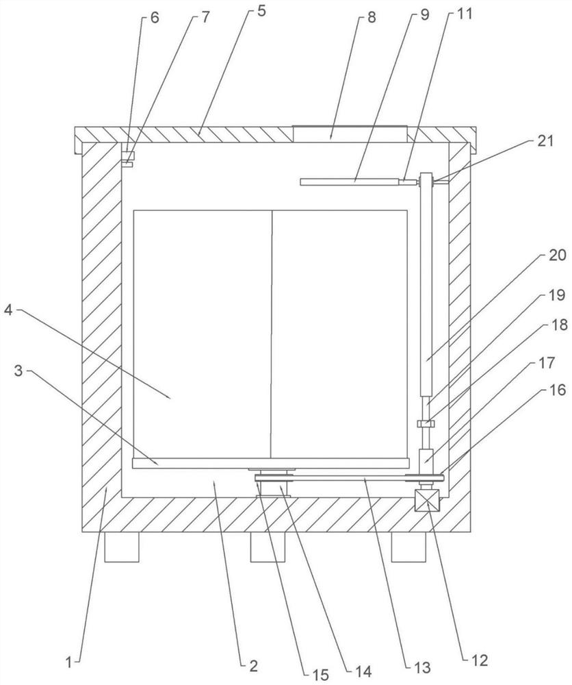
[0031] Such as figure 2As shown, the difference between this embodiment and Embodiment 1 is that this embodiment also includes a transmission part, which includes a screw 19 , a threaded part, a rack 20 and a gear 21 , and the threaded part in this embodiment is a nut 18 . One end of the screw rod 19 is a polished rod, and the lower end of the rack 20 is rotationally connected with the end of the polished rod of the screw rod 19. The connection method is the prior art, known to those skilled in the art, and will not be repeated here. The screw rod 19 passes through the nut 18 and is threadedly engaged with the nut 18 , and the nut 18 is welded to the inner wall of the housing 1 . There is a cavity on the top of the rotating shaft 17, and a protrusion is welded on the side wall of the cavity. The side wall of the screw rod 19 is provided with a sliding groove, and the screw rod 19 extends into the cavity and can slide and fit with the cavity; the protrusion snaps into the sli...

Embodiment 3

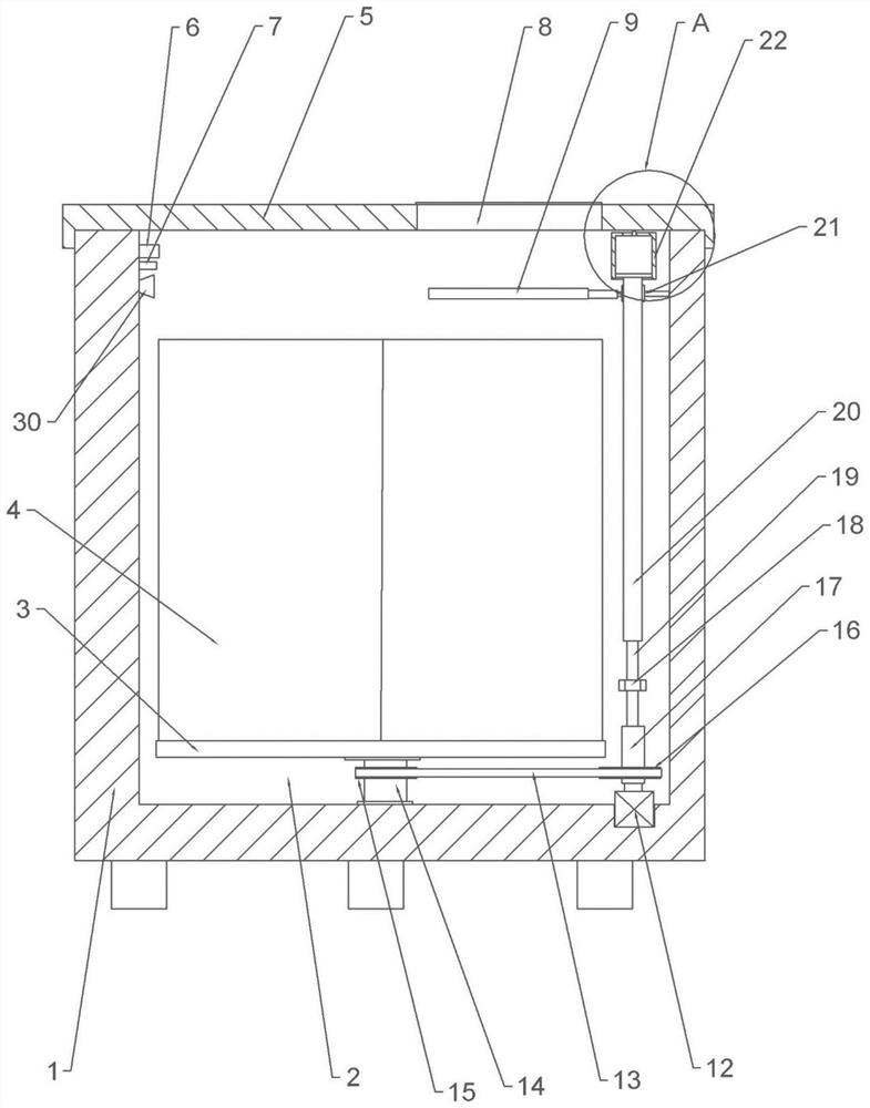
[0036] Such as image 3 and Figure 4 As shown, the difference between this embodiment and Embodiment 1 is that a disinfection structure is also provided in this embodiment. The disinfection structure includes a cylinder body 22 , a connecting pipe (not shown in the figure) and a nozzle 30 , the nozzle 30 is clamped on the side wall of the recovery cavity 2 and the nozzle 30 is located above the recovery bucket 4 . The number of shower heads 30 can be multiple ( image 3 only one of them is shown). The cylinder body 22 is welded on the upper part of the side wall of the recovery chamber 2, the cylinder body 22 is a liquid storage chamber 23, the liquid storage chamber 23 is filled with disinfectant and the liquid storage chamber 23 is sealed and slidingly connected with a piston 24, the lower end of the piston 24 is connected to the rack 20 upper ends are clamped. The upper end of the cylinder body 22 is provided with a liquid outlet 25, and the two ends of the communicati...

Embodiment 4

[0039] Such as Figure 5 and Figure 6 As shown, the difference between the present embodiment and the third embodiment is that the present embodiment also includes a suction pump (not shown in the figure), a suction pipe 33, a baffle plate 28, a connecting rod 29 and a casing 32, the casing 32 covers are arranged on the lower end of the receiving plate 9 and form a relatively sealed area with the receiving plate 9. The lower end of the casing 32 is connected with the suction pipe 33, and the suction pipe 33 is connected with the suction pump. The connection methods are all in the prior art. This will not be repeated here. A plurality of suction ports 26 are evenly opened on the upper end surface of the receiving plate 9, and the suction ports 26 pass through the receiving plate 9, and a cylinder 31 is fixed on the lower end of the receiving plate 9 by screws, and the output shaft of the cylinder 31 is clamped with one end of the connecting rod 29 , the other end of the conn...


PUM


Abstract

The invention relates to the field of garbage classification devices, in particular to an intelligent garbage classification device. The intelligent garbage classification device comprises a shell, arotary shaft, a controller and a power mechanism driving the rotary shaft to rotate; the upper end of the shell is provided with an inlet, and the interior of the shell is provided with a recycling cavity; the rotary shaft is located in the recycling cavity and rotationally connected with the shell, the rotary shaft is coaxially provided with a supporting plate, and the supporting plate is provided with a plurality of recycling barrels; the upper portion of the recycling cavity is rotationally connected with a receiving plate, and the receiving plate is located above the recycling barrels, andthe rotation axis of the receiving plate is perpendicular to the rotary shaft; and the upper portion of the recycling cavity is provided with a recognition mechanism for recognizing types of garbage,the recognition mechanism is electrically connected with a controller, and the controller can control a power mechanism. By adopting the intelligent garbage classification device, intelligent classification of garbage can be achieved, and the situation of wrong throwing of garbage is reduced and even avoided.

Description

technical field [0001] The invention relates to the field of garbage sorting devices, in particular to an intelligent garbage sorting device. Background technique [0002] With the development of the economy and the increase of the population, more and more garbage is produced in people's daily life. It has become more and more difficult to deal with the garbage effectively and in a timely manner by the previous methods of landfill or incineration. Sorting garbage is a way to improve the resource value and economic value of garbage, and strive to make the best use of it. Sorting garbage collection can reduce the amount of garbage disposal and processing equipment, reduce processing costs, reduce land resource consumption, and have social, economic, and ecological benefits. From a large perspective, garbage can be divided into two categories: recyclable garbage and non-recyclable garbage. When people put in garbage, it is often difficult to distinguish whether the garbage t...

Claims


Application Information

Patent Timeline
Patent Type & Authority Applications(China)
IPC IPC(8): B65F1/14B65F1/00B65F7/00G06K9/62
CPCB65F1/14B65F1/006B65F7/00B65F2210/138B65F2210/176G06F18/24Y02W30/10
Inventor 丁志强张本均
Owner CHONGQING VOCATIONAL INST OF ENG
Features
  • R&D
  • Intellectual Property
  • Life Sciences
  • Materials
  • Tech Scout
  • Unparalleled Data Quality
  • Higher Quality Content
  • 60% Fewer Hallucinations
Learn More