Vision inspection device for appearance defects of rollers

A visual inspection device and a technology for appearance defects, applied in the field of visual inspection, can solve problems such as inability to detect bearing rollers, achieve automation and intelligence, and improve accuracy and efficiency

Active Publication Date: 2015-09-09
临清市万达轴承有限公司
View PDF9 Cites 29 Cited by
  • Summary
  • Abstract
  • Description
  • Claims
  • Application Information

AI Technical Summary

Problems solved by technology

In order to realize the automatic detection of the appearance of bearing rollers, it is necessary to conduct a comprehensive inspection of bearing rollers. However, the current machine vision automatic inspection equi

Method used


Image

  • Vision inspection device for appearance defects of rollers
  • Vision inspection device for appearance defects of rollers
  • Vision inspection device for appearance defects of rollers

Examples


Embodiment 1

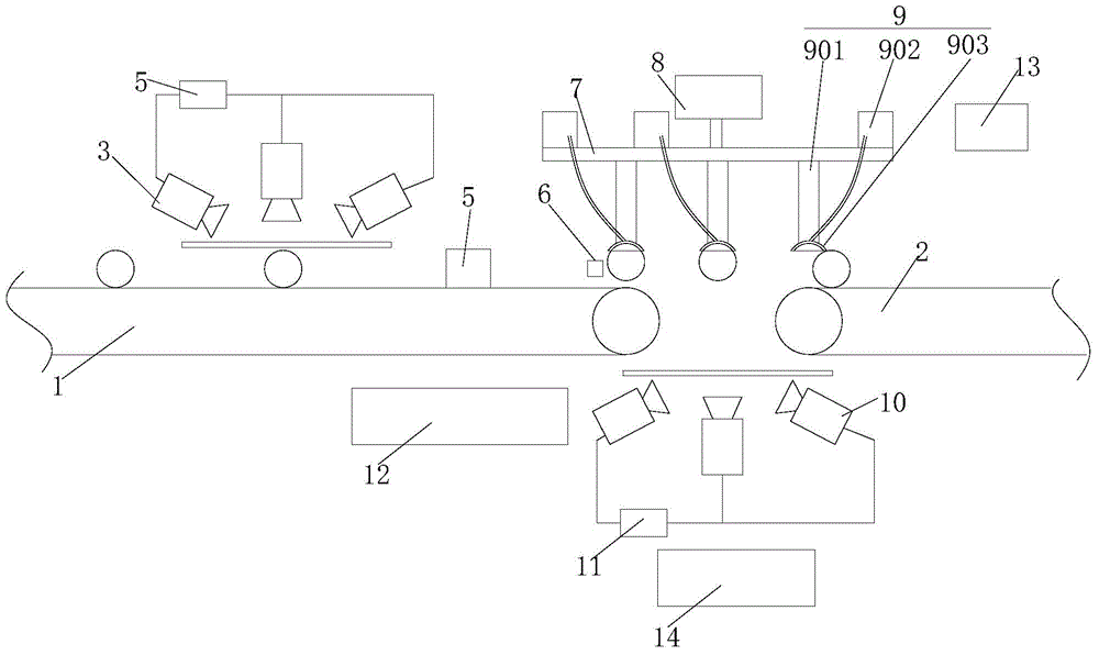
[0031] refer to figure 1 , a visual detection device for roller appearance defects proposed by the present invention, comprising a first conveyor belt 1, a second conveyor belt 2, a first image taking device 3, a first image processing system 4, a first product rejecting device 5, an optical sensor 6. Turntable 7, turntable driving device 8, three roller suction devices 9, second imaging device 10, second image processing system 11 and control device 13;

[0032] The first imaging device 4 and the first product rejecting device 5 are arranged above the first conveyor belt 1 and arranged in sequence along the conveying direction of the first conveyor belt 1, and the first imaging device 4 is connected to the first image processing system 4;

[0033] The turntable 7 and three sets of roller suction devices 9 are arranged between the first conveyor belt 1 and the second conveyor belt 2, and above the first conveyor belt 1 and the second conveyor belt 2, the turntable 7 is driven ...

specific Embodiment 2

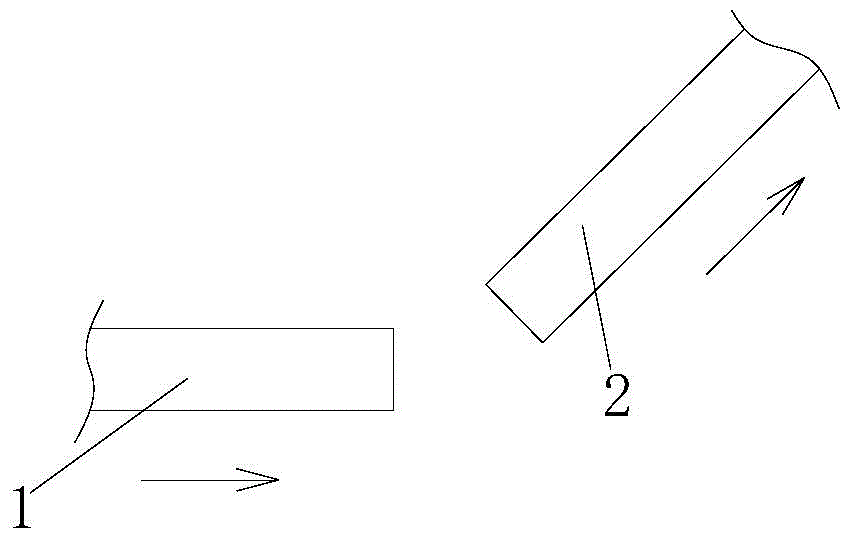
[0051] The main technical solution of this embodiment is the same as that of Embodiment 1, and will not be repeated here. The difference is that, refer to figure 2 , the first conveyor belt 1 and the second conveyor belt 2 are arranged crosswise to make reasonable use of the occupied space.

specific Embodiment 3

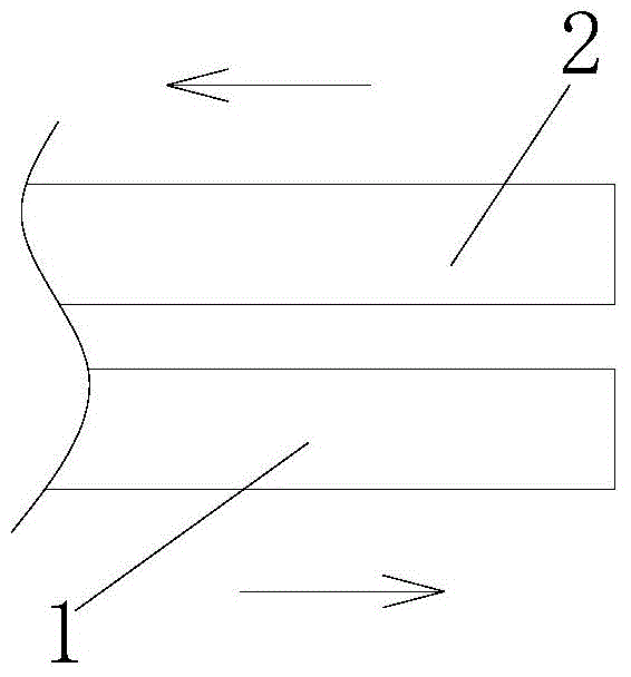
[0052] The main technical solution of this embodiment is the same as that of Embodiment 1, and will not be repeated here. The difference is that, refer to image 3 , the first conveyor belt 1 and the second conveyor belt 2 are arranged oppositely and side by side, so that the space occupied by the visual inspection device in the length direction can be reduced, which is beneficial to the rational use of space.


PUM


Abstract

The invention discloses a vision inspection device for appearance defects of rollers, and relates to the technical field of vision inspection devices. The device comprises a first conveying belt, a second conveying belt, a first image device, a first image processing system and a first inferior-quality product removing device and further comprises a rotating disc, a rotating disc driving device, roller sucking devices, a second image capturing device and a second image processing system. The first conveying belt conveys rollers to be inspected, the second conveying belt conveys qualified rollers, and the first image capturing device, the first image processing system and the first inferior-quality product removing device inspect the appearance defects of the upper sides of the rollers and remove unqualified inferior-quality products; and the rotating disc, the rotating disc driving device, the roller sucking devices, the second image capturing device and the second image processing system are used for inspecting the appearance defects of the lower sides of the rollers and remove the unqualified inferior-quality products. Vision inspection can be comprehensively carried out on the rollers in a no-dead-corner manner, and meanwhile, the unqualified inferior-quality products are removed; and automation and intelligence of the whole process are achieved, and precision and efficiency of roller inferior-quality product inspection can be improved.

Description

technical field [0001] The invention relates to the technical field of visual inspection, in particular to a visual inspection device for roller appearance defects. Background technique [0002] The roller in the roller bearing is an important rolling part, and the quality of the roller directly affects the quality and life of the bearing. The rollers are often in the shape of short cylinders, cones or waist drums. Bearing rollers require strict inspection of appearance, including external dimensions, external defects, etc. At present, the commonly used method is manual random inspection, which has problems such as low efficiency and low defect detection rate. Appearance visual inspection device is a special equipment that uses machine vision to detect the appearance size and defects of objects. In order to realize the automatic detection of the appearance of bearing rollers, it is necessary to conduct a comprehensive inspection of bearing rollers. However, the current mac...

Claims


Application Information

Patent Timeline
IPC IPC(8): B07C5/342G01N21/88
Inventor 吕月林戚亚明
Owner 临清市万达轴承有限公司
Why Eureka
Try Eureka