
Visual inspection equipment with double-limiting structure

A limit structure and visual inspection technology, applied in the field of visual inspection, can solve problems such as inability to adapt to different machine tool inspection positions, lack of telescopic adjustment and up and down movement structures, and inability to perform visual inspection, so as to achieve traction balance and increase brightness , the effect of increasing brightness

Inactive Publication Date: 2020-03-24
DONGGUAN UNIV OF TECH
View PDF10 Cites 1 Cited by
  • Summary
  • Abstract
  • Description
  • Claims
  • Application Information

AI Technical Summary

Problems solved by technology

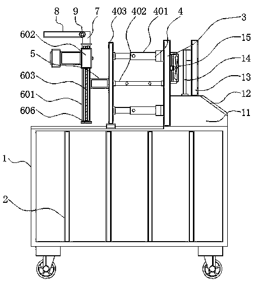
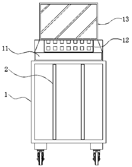
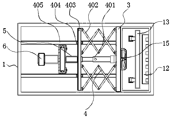
[0004] The object of the present invention is to provide a visual detection device with a double-positioning structure, so as to solve the problem that the image acquisition mechanism provided by the existing visual detection device proposed in the above-mentioned background technology generally does not have a convenient telescopic adjustment and up-and-down movement structure, It cannot adapt to different machine tool detection positions, and there is no corresponding limit structure when adjusting the movement, and it does not have the function of supplementary light, so it is impossible to carry out effective visual inspection in the case of insufficient light

Method used


Image

  • Visual inspection equipment with double-limiting structure
  • Visual inspection equipment with double-limiting structure
  • Visual inspection equipment with double-limiting structure

Examples


Embodiment Construction

[0026] The technical solutions in the embodiments of the present invention will be clearly and completely described below in conjunction with the accompanying drawings in the embodiments of the present invention. Obviously, the described embodiments are only some of the embodiments of the present invention, not all of them. Based on The embodiments of the present invention and all other embodiments obtained by persons of ordinary skill in the art without making creative efforts belong to the protection scope of the present invention.

[0027] In the description of the present invention, unless otherwise stated, the meaning of "plurality" is two or more; the terms "upper", "lower", "left", "right", "inner", "outer" , "front end", "rear end", "head", "tail", etc. indicate the orientation or positional relationship based on the orientation or positional relationship shown in the drawings, and are only for the convenience of describing the present invention and simplifying the desc...


PUM


Abstract

The invention discloses visual inspection equipment with a double-limiting structure, and relates to the technical field of visual inspection. The equipment comprises a machine body, an image acquisition mechanism, a light supplementing mechanism and a display screen. A reinforcing plate is fixed on the outer side of the machine body. A fixed plate is mounted on one side of the upper part of the machine body. A telescopic adjusting structure is mounted on one side of the fixed plate. A connecting rod is fixed to one side of the telescopic adjusting structure. The image acquisition mechanism ismounted on one side of the connecting rod. A connecting plate is arranged above the connecting rod. A light supplementing plate is mounted on one side of the connecting plate. A hinge is arranged between the light supplementing plate and the connecting plate. The light supplementing mechanism is mounted below the light supplementing plate. The equipment has the advantages that by arranging the telescopic adjusting structure, telescopic adjustment of the position of the image acquisition mechanism is facilitated, and by arranging the electric push rod, movement of the push plate is facilitated, so that adjustment of the position of the image acquisition mechanism is facilitated.

Description

technical field [0001] The invention relates to the technical field of visual inspection, in particular to a visual inspection device with a double limit structure. Background technique [0002] Visual inspection is to use machines instead of human eyes for measurement and judgment. Visual inspection refers to converting the captured target into image signals through machine vision products (ie, image capture devices, divided into CMOS and CCD), and sending them to dedicated image processing. The system, according to the pixel distribution, brightness, color and other information, is converted into a digital signal; the image system performs various operations on these signals to extract the characteristics of the target, and then controls the on-site equipment action according to the result of the discrimination. It is used for production and assembly. Or a valuable mechanism of packaging that is invaluable in its function of detecting defects and preventing defective produ...

Claims


Application Information

Patent Timeline
Patent Type & Authority Applications(China)
IPC IPC(8): G01N21/84G01N21/01
CPCG01N21/01G01N21/84G01N2021/0112
Inventor 魏亚东吴云霞周飞凌东雄
Owner DONGGUAN UNIV OF TECH
Learn More