Eureka AIR delivers breakthrough ideas for toughest innovation challenges, trusted by R&D personnel around the world.

Automatic chip pipe placing direction adjusting device

A technology that automatically adjusts the device and placement direction. It is used in transportation and packaging, conveyors, conveyor objects, etc., and can solve problems such as equipment alarms, labor costs, and test stoppages.

Pending Publication Date: 2020-11-13
广东利扬芯片测试股份有限公司
View PDF12 Cites 0 Cited by
  • Summary
  • Abstract
  • Description
  • Claims
  • Application Information

AI Technical Summary

Problems solved by technology

Since the existing IC testing machine requires the bottom (pin) of the IC chip to face downward when performing the IC chip test, that is, the direction of the groove of the material pipe is required to be downward, and there is a lack of corresponding equipment in the prior art to adjust the direction of the material pipe. The direction of placement can only be arranged manually on the feeding equipment one by one, which is inefficient and requires high labor costs. Sometimes the wrong direction of the material tubes will cause the equipment to alarm, stop testing, and even damage the product. , adversely affect the test efficiency and product quality of IC chips

Method used


Image

  • Automatic chip pipe placing direction adjusting device
  • Automatic chip pipe placing direction adjusting device
  • Automatic chip pipe placing direction adjusting device

Examples


Embodiment Construction

[0016] In order to describe the technical content, structural features, and achieved effects of the present invention in detail, the following will be described in detail in conjunction with the embodiments and accompanying drawings.

[0017] In the description of the present invention, it should be understood that the orientation or positional relationship indicated by the terms "upper", "lower", "top", "bottom", "outer" etc. is based on the orientation or positional relationship shown in the drawings , is only for the convenience of describing the present invention and simplifies the description, and thus cannot be construed as limiting the protection content of the present invention.

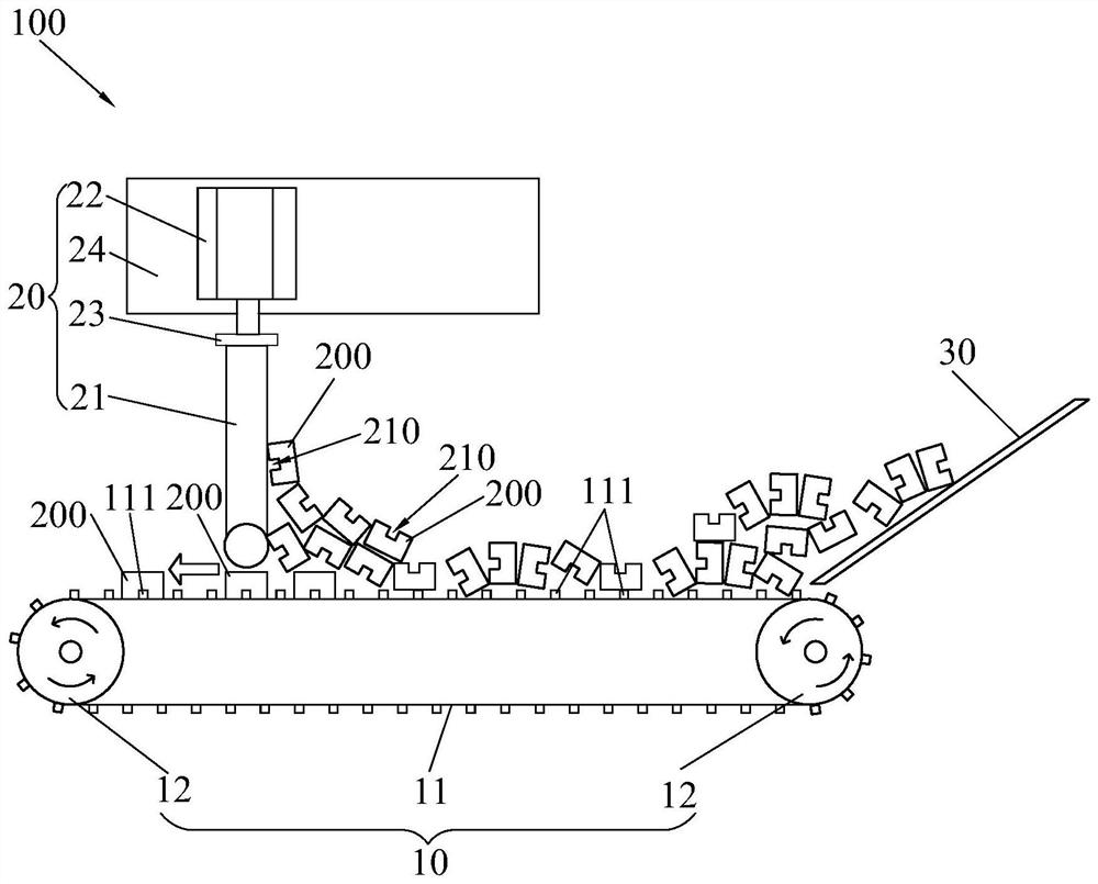
[0018] The invention discloses an automatic adjustment device 100 for placing the direction of the material tube of a chip, which is suitable for adjusting the placing direction of the material tube 200 with a groove 210, and the direction of the material tube 200 is uniformly placed with the ...


PUM


Abstract

The invention discloses an automatic chip pipe placing direction adjusting device which is suitable for adjusting the placing direction of a pipe with grooves and comprises a conveying structure and ablocking structure; the conveying structure is used for conveying the pipe; a plurality of bulges are distributed on the conveying structure at intervals in the conveying direction of the conveying structure and are matched with the grooves; the distance between every two adjacent bulges is less than the width of the pipe and is greater than the distance between the side wall of the groove and the outer side wall of the pipe; the blocking structure comprises a blocking piece above the conveying structure; a distance exists between the blocking piece and the conveying structure; and when the grooves and the bulges are embedded, the pipe can pass through below the blocking piece; otherwise, the pipe is blocked by the blocking piece. The automatic chip pipe placing direction adjusting deviceadjusts the placing direction of the pipe to a preset direction (with the grooves being downwards) in a unified manner, replaces the manner that the grooves of the pipe are downwards to be arrayed onfeeding equipment one by one, reduces the labor cost and ensures that the placing direction of the pipe is correct.

Description

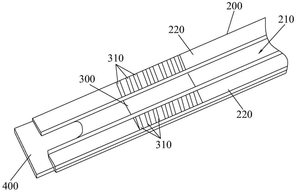
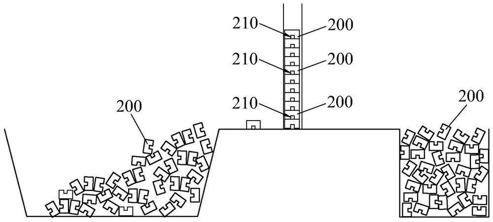
technical field [0001] The invention relates to the technical field of chip testing, in particular to a device for automatically adjusting the placement direction of a chip material tube. Background technique [0002] There are many packaging methods for IC (Integrated Circuit Integrated Circuit) chips, and one of the more widely used packaging methods is packaging through material tubes. Such as figure 1 As shown, the material tube 200 is in the shape of a strip, and the middle part of a plane corresponding to the bottom of the chip 300 is recessed toward the opposite surface to match the shape of the IC chip 300 , and a groove 210 is formed at the recessed part. When packaging the IC chips 300, the IC chips 300 are sequentially discharged in the material tube 200, and then the two ends of the material tube are sealed by two plugs 400 respectively. [0003] In order to ensure the quality of IC chips, IC chips must undergo performance tests before leaving the factory, incl...

Claims


Application Information

Patent Timeline
IPC IPC(8): B65G15/42B65G47/26B65G47/88
CPCB65G15/42B65G47/26B65G47/8815
Inventor 陈勇郭敦风贾鹏方琪雷垒袁俊张亦锋辜诗涛卢旭坤郑朝生
Owner 广东利扬芯片测试股份有限公司
Why Eureka
Eureka Blog
Learn More