Dewatering well plugging structure with water and construction method thereof

A construction method and technology for dewatering wells, which are applied in infrastructure engineering, construction, etc., can solve problems such as failure of concrete pouring, influence of bolt reinforcement effect, deformation and damage of flanges, etc., to improve waterproof effect, good practicability, and finished products. Protect the simple effect

Inactive Publication Date: 2020-11-13
ZHONGTIAN CONSTR GROUP
View PDF3 Cites 3 Cited by
  • Summary
  • Abstract
  • Description
  • Claims
  • Application Information

AI Technical Summary

Problems solved by technology

[0003] The present invention provides a water-carrying plugging structure and construction method of a dewatering well to solve the problem that the existing technology of the dewatering well sealing structure and method adopting the installation of the flange plate encounters the situation that the groundwater is abundant, and the dewatering well cannot In relatively dry construction conditions, flanges are likely to be deformed and damaged, which affects the bolt reinforcement effect, making concrete pouring impossible, and eventually the well sealing fails and leakage occurs

Method used


Image

  • Dewatering well plugging structure with water and construction method thereof
  • Dewatering well plugging structure with water and construction method thereof

Examples


Embodiment 1

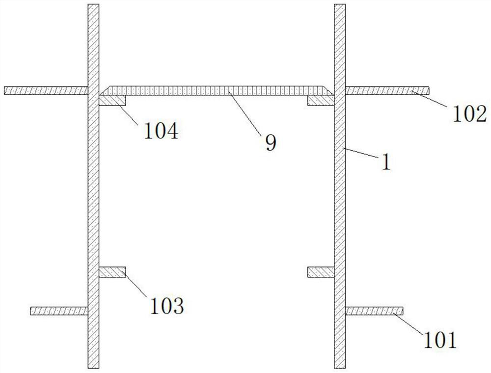
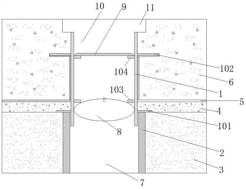
[0027] A water-filled sealing structure for a dewatering well, comprising a longitudinal tubular steel sleeve 1, the lower end of the steel sleeve 1 extends into the upper end of the downcomer 2, and the outer wall of the steel sleeve 1 is sequentially sleeved and connected with Ring plate-shaped lower wing ring plate 101 and upper wing ring plate 102, the lower wing ring plate 101 is placed at the upper end nozzle of the downcomer 2, the downcomer 2 below the lower wing ring plate 101 is arranged in the base layer 3, the lower wing The steel sleeve 1 above the ring plate 101 is filled with concrete cushion 4, waterproof layer 5 and floor concrete 6 from bottom to top, the upper wing ring plate 102 is located in the bottom plate concrete 6; the lower wing ring plate 101 and the upper wing ring plate 102 The inner wall of the steel sleeve 1 at the place is respectively connected with a ring-shaped lower water-stop ring plate 103 and an upper water-stop ring plate 104, the downco...

Embodiment 2

[0042] A water-carrying plugging structure for a dewatering well is similar to Embodiment 1, except that the inflatable bag 8 is a rubber air bag.

[0043] It is also possible that the longitudinal centerlines of the steel sleeve 1 , the downcomer 2 , the lower wing ring plate 101 and the upper wing ring plate 102 , the lower water stop ring plate 103 and the upper water stop ring plate 104 are all coincident.

[0044] The water-carrying plugging structure of the dewatering well of the present invention and its construction method are convenient and reliable through the use of rubber inflatable bags 8 and concrete layered pouring, and the construction materials are economical and environmentally friendly, and water-proof operations are realized. In specific waterproof construction , the waterproof material is on the water-facing surface, and its waterproof effect is better than that of the back-water surface, so that it can be blocked when there is water. Generally, the inflati...


PUM


Abstract

The invention discloses a dewatering well plugging structure with water and a construction method thereof. The lower end of a steel sleeve of the plugging structure extends into the upper end of a dewatering pipe. The outer wall of the steel sleeve is connected with a lower wing ring plate and an upper wing ring plate. The portions, at the positions of the lower wing ring plate and the upper wingring plate, of the inner wall of the steel sleeve are connected with a lower water stopping ring plate and an upper water stopping ring plate which are each in an annular plate shape correspondingly.The dewatering pipe is internally filled with clay or gravel. The portion, above the clay or gravel, of the steel sleeve is internally provided with an inflatable bag. The top face of the inflatable bag is located above the lower water stopping ring plate. The transverse center line of the inflatable bag is located below the lower water stopping ring plate. A steel cover plate is welded to the upper water stopping ring plate. The contact faces between the upper water stopping ring plate and the steel cover plate form a full weld structure. The portion, between the steel cover plate and the inflatable air bag, of the steel sleeve and the portion, above the steel cover plate, of the steel sleeve both internally filled with expanding impermeable concrete. The top layer of the expanding impermeable concrete is a tongue-and-groove joint undergoing roughening treatment. The dewatering well plugging structure with water is easy to operate, wide in application range and good in plugging effect, stops a water body from rising, and improves the well plugging waterproof effect.

Description

technical field [0001] The invention belongs to the technical field of buildings, and in particular relates to a water-carrying plugging structure for a dewatering well and a construction method thereof. Background technique [0002] At present, the construction of deep foundation pit dewatering projects is increasing day by day, and the sealing construction after the dewatering well directly affects the construction quality of underground engineering. The existing dewatering well sealing method mostly adopts the method of installing flanges, and then uses bolts and rubber pads to seal; However, if there is abundant groundwater, relatively dry construction conditions cannot be achieved in the dewatering well, and the flange plate is prone to deformation and damage, which affects the bolt reinforcement effect, making concrete pouring impossible, and eventually the well closure fails and leakage occurs. Contents of the invention [0003] The present invention provides a wate...

Claims


Application Information

Patent Timeline
IPC IPC(8): E02D19/22E02D19/10
CPCE02D19/10E02D19/22
Inventor 王佳玉刘玉涛陈诚陈永伟王左同赵树山陈赛菊赵宗元肖培磊陈默吴硕军朱彬马
Owner ZHONGTIAN CONSTR GROUP
Why Eureka
Try Eureka