AI technical title is built by Patsnap AI team. It summarizes the technical point description of the patent document.
An integral and bottom plate technology, applied in the bathroom field, can solve problems such as reducing the anti-skid effect, and achieve the effect of preventing loosening.
Active Publication Date: 2020-11-13
胡敬伟 +1
View PDF10 Cites 1 Cited by
Summary
Abstract
Description
Claims
Application Information
AI Technical Summary
This helps you quickly interpret patents by identifying the three key elements:
Problems solved by technology
Method used
Benefits of technology
Problems solved by technology
[0004] When the splicing base plate is tiled and spliced, it will encounter corners and other positions, which need to be cut. A single base plate is composed of multiple small bodies. After trimming, the joints around the periphery will be separated, making the single base plate appear Loose, reducing its anti-slip effect
Method used
Image
Click on the blue label to locate the original text in one second.
Reading with bidirectional positioning of images and text.
Examples
Embodiment 1
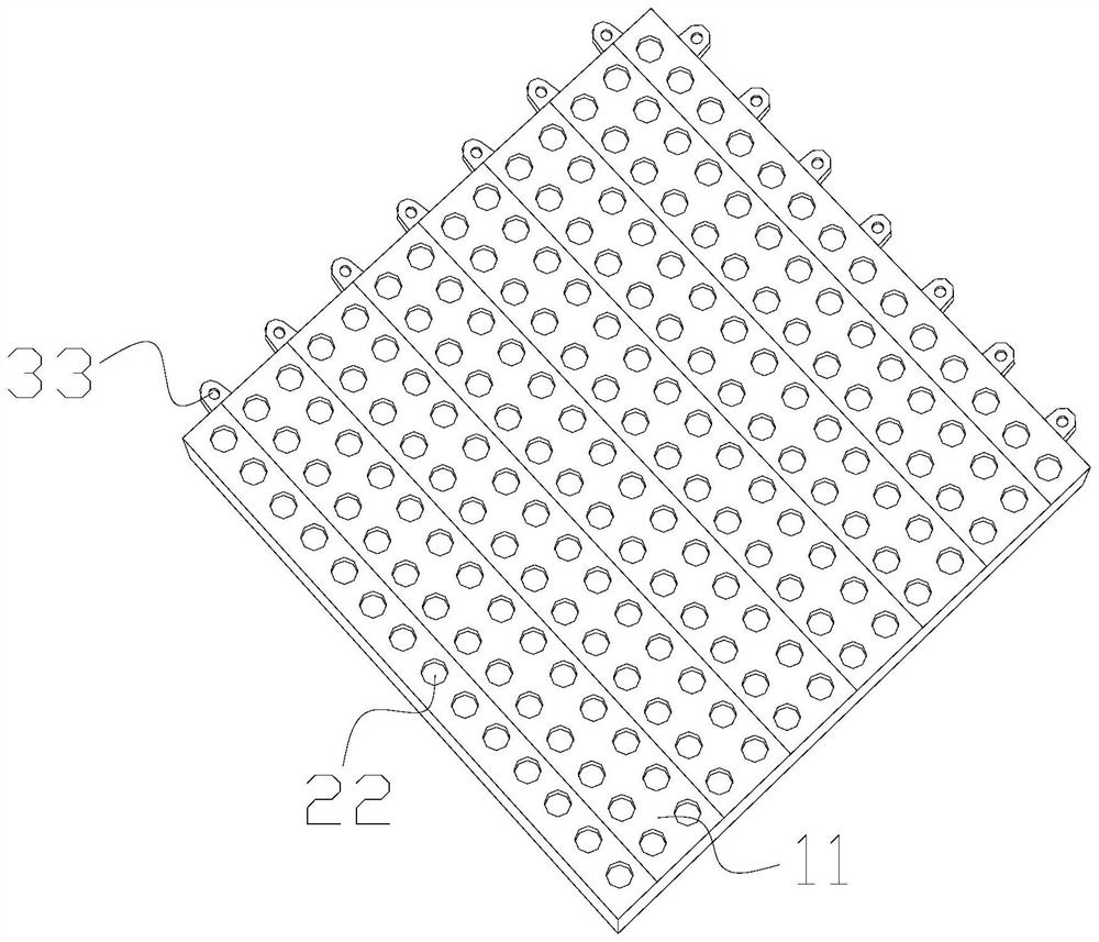
[0032] as attached figure 1 to attach Image 6 Shown:
[0033] The present invention provides an integral bathroom splicing floor, the structure of which includes a main panel 11, a port 22, and a buckle 33, the port 22 and the main panel 11 are an integrated structure, and the buckle 33 is fixed Jigsaw 11 outer surfaces.
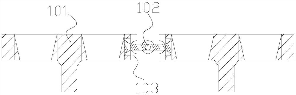
[0034] The main panel 11 includes a strut 101 , a pulling core 102 , and a joint 103 , the joint 103 and the strut 101 are an integrated structure, and the pulling core 102 penetrates between the joints 103 .
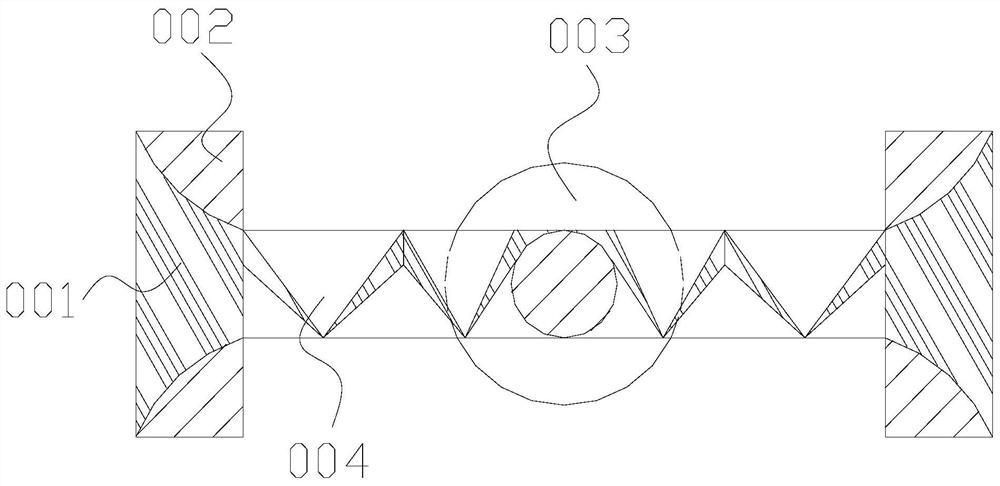
[0035] Wherein, the pulling core 102 includes a solid head 001, an outer solid block 002, a middle ball 003, and a brace 004, the solid head 001 is fixed between two outer solid blocks 002, and the brace 004 is installed on the solid head 001, the middle ball 003 is connected with the tie bar 004, the tie bar 004 is evenly connected in the horizontal direction, the middle ball 003 is a spherical structure, and the fixed head 001 fixes the stress p...
Embodiment 2
[0042] as attached Figure 7 to attach Figure 9 Shown:
[0043] Wherein, the middle ball 003 includes an outer ring g1, a blank holder g2, a blank g3, and a central core g4, the blank g3 and the outer ring g1 are of an integrated structure, and the central core g4 and the outer ring g1 are located on the same axis On the center, the blank holder g2 is against the inner wall of the outer ring g1, the center core g4 is a spherical structure, the outer ring g1 limits the installation range inside, the center core g4 fixes the hard force of the center, the Blankholder g2 supports the supporting force of the outer layer.
[0044]Wherein, the clamping edge g2 includes a hard block 511, an arc body 512, and a limiting edge 513, the hard block 511 and the arc body 512 are an integrated structure, the limiting edge 513 is attached to the outer surface of the arc body 512, and the There are two hard blocks 511, the arc body 512 is an arc structure, the arc body 512 supports the forc...
PUM
Abstract
The invention discloses a unit bathroom splicing type bottom plate. The unit bathroom splicing type bottom plate structurally comprises main splicing plates, through openings and buckles, wherein thethrough openings and the main splicing plates are of an integrated structure, the buckles are fixed to the outer surfaces of the main splicing plates, and when the main splicing plates are trimmed, pulling cores connected between the main splicing plates are distributed and installed according to the intervals of the through openings; the pulling cores connected between supporting rods can move positions of close ports, the center positions of the middles are fixed through middle balls, thereby providing a certain moving space for connecting parts; arc strips can play a certain degree of extension according to pulling of pulling-back strips, and when the bottom plate is trimmed into the needed shape, the tenacity is properly stretched for good trimming, and the loosening of the bottom plate is prevented; an outer ring of a shell of each internal middle ball can be extruded by the outer side, the position of each core is fixed by the middle core, the hard force of the center is fixed, the movement range is limited to the maximum extent by a limiting edge, and the pulling positions can be extruded to abut against the relative position in a counter-force mode when the joint parts arecombined.
Description
technical field [0001] The invention belongs to the field of sanitary ware, and more specifically relates to an integral sanitary ware splicing bottom plate. Background technique [0002] In order to achieve the anti-skid effect, the floor of the bathroom is tiled and spliced with the bottom plate. On the basis of the floor, a layer of anti-skid bottom plate is added to prevent slipping, and the bottom plate is spliced according to the edge shape of the bathroom. [0003] Based on the above-mentioned discovery by the present inventors, the existing bathroom splicing floor mainly has the following deficiencies, such as: [0004] When the splicing base plate is tiled and spliced, it will encounter corners and other positions, which need to be cut. A single base plate is composed of multiple small bodies. After trimming, the joints around the periphery will be separated, making the single base plate appear Loose shape reduces its anti-slip effect. [0005] Therefore need ...
Claims
Application Information
Patent Timeline
Application Date:The date an application was filed.
Publication Date:The date a patent or application was officially published.
First Publication Date:The earliest publication date of a patent with the same application number.
Issue Date:Publication date of the patent grant document.
PCT Entry Date:The Entry date of PCT National Phase.
Estimated Expiry Date:The statutory expiry date of a patent right according to the Patent Law, and it is the longest term of protection that the patent right can achieve without the termination of the patent right due to other reasons(Term extension factor has been taken into account ).
Invalid Date:Actual expiry date is based on effective date or publication date of legal transaction data of invalid patent.

