Magnetic steel module, rotor house and rotor assembly

A module and magnetic steel technology, which is applied in the direction of magnetic circuit rotating parts, electric components, magnetic circuits, etc., can solve the problems of magnetic steel modules such as loose fixation, abnormal operation noise or loosening, so as to avoid loosening, Avoid abnormal noise and avoid the effect of bolt loosening

Pending Publication Date: 2022-03-01
SHANGHAI ELECTRIC WIND POWER GRP CO LTD +1
View PDF0 Cites 0 Cited by
  • Summary
  • Abstract
  • Description
  • Claims
  • Application Information

AI Technical Summary

Problems solved by technology

[0006] The technical problem to be solved by the present invention is to provide a magnetic steel module, rotor house and rotor assembly

Method used


Image

  • Magnetic steel module, rotor house and rotor assembly
  • Magnetic steel module, rotor house and rotor assembly
  • Magnetic steel module, rotor house and rotor assembly

Examples


Embodiment 1

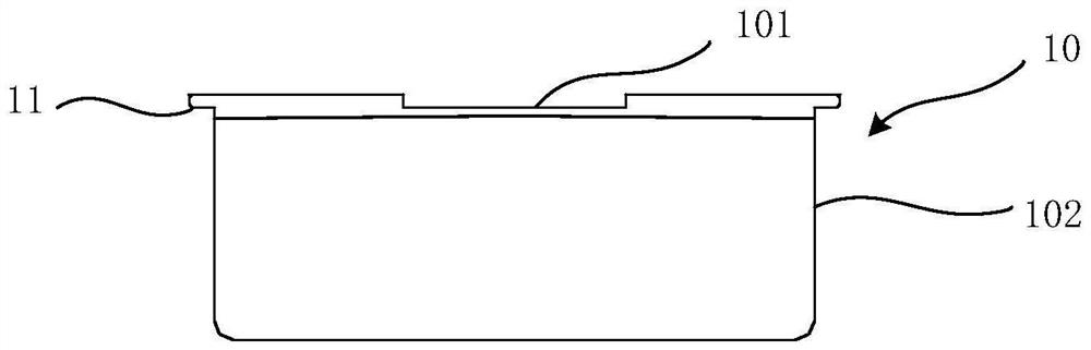
[0053] Such as Figure 1 to Figure 4 As shown, this embodiment provides a rotor assembly 30, the rotor assembly 30 includes a magnetic steel module 10 and a rotor house 20, the magnetic steel module 1 is fixed on the rotor house 20, and the magnetic steel module 10 includes a The substrate 15 in contact with the yoke surface, the substrate 15 is made of magnetically permeable material, and has a first groove 101 on the side facing the yoke surface, the first groove 101 is connected to the magnetic steel module 10 and the yoke surface A gap is formed between them to reduce the contact area between the yoke surface and the substrate 15 . The magnetic steel module 10 also includes a cover plate 12, a magnetic steel 13, a magnetic steel frame 14 and a silicon steel part (not shown in the figure), wherein the silicon steel part is arranged between the magnetic steel 13 and the base plate 15, and the upper and lower parts of the silicon steel part The two ends are respectively in c...

Embodiment 2

[0066] This embodiment provides a rotor assembly 30 , which adopts the same principle as Embodiment 1. The difference is that in this embodiment, grooves are made on the yoke surface of the rotor house 20 , while the magnetic steel module 10 does not have grooves.

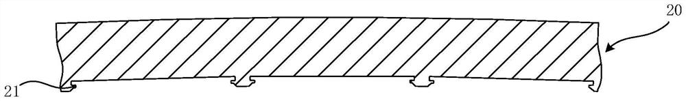
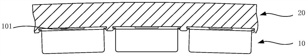
[0067] Such as Figure 5 to Figure 8 As shown, a rotor house 20, the rotor house 20 includes a yoke surface in contact with the magnetic steel module 10, a second groove 201 is opened on the yoke surface, and the second groove 201 makes the yoke surface and the magnetic steel mold Gaps are formed between the groups 10 to reduce the contact area between the yoke face and the substrate 15 .

[0068] In this embodiment, there is one second groove 201 , and the shape of the second groove 201 projected on the yoke surface is a waist-shaped groove extending along the axis of the rotor house 20 . It should be noted that the number, shape and size of the grooves are not specifically limited here, and it can be multiple gr...


PUM


Abstract

The invention discloses a magnetic steel module, a rotor house and a rotor assembly. Wherein the magnetic steel module comprises a substrate in contact with a magnet yoke surface of the rotor room, a groove is formed in one side, facing the magnet yoke surface, of the substrate, and a gap is formed between the magnetic steel module and the magnet yoke surface through the groove, so that the contact area of the magnet yoke surface and the substrate is reduced. The rotor room comprises a magnet yoke surface in contact with the magnetic steel module, the magnet yoke surface is provided with a groove, and the groove enables a gap to be formed between the magnet yoke surface and the magnetic steel module so as to reduce the contact area of the magnet yoke surface and the substrate. According to a Maxwell electromagnetic attraction force formula, the smaller the contact area of the magnetic steel module substrate and the magnet yoke surface of the rotor room is, the larger the electromagnetic attraction force is, so that the contact area of the substrate and the magnet yoke surface of the rotor room is reduced by forming the grooves in any one or both of the magnetic steel module substrate and the magnet yoke surface of the rotor room; therefore, the electromagnetic attraction force larger than the original electromagnetic attraction force can be obtained, and the phenomenon that abnormal sound is generated or the bolt is loosened during operation of the motor can be avoided.

Description

technical field [0001] The invention belongs to the field of permanent magnet direct drive wind power generators, and in particular relates to a magnetic steel module, a rotor house and a rotor assembly. Background technique [0002] The rotor magnets of the outer rotor permanent magnet direct-drive wind turbines are usually surface-mounted to fix the magnets on the yoke surface of the inner wall of the rotor. [0003] The operating environment of wind turbines is often a high-humidity, high-salt environment, especially offshore wind turbines, where the operating conditions are relatively harsh. In order to prevent the oxidation and corrosion of the magnets, the current common practice is to encapsulate the magnets in metal non-magnetic materials (stainless steel ) and the substrate made of metal magnetic permeable material (low carbon steel plate), which are called magnetic steel components. The fixing methods of magnetic steel components mainly include slot fixing and bol...

Claims


Application Information

Patent Timeline
Patent Type & Authority Applications(China)
IPC IPC(8): H02K1/2786H02K1/2791H02K1/28
CPCH02K1/2786H02K1/28H02K2213/03
Inventor 孙永岗钟云龙卢江跃吴立建翟东伟
Owner SHANGHAI ELECTRIC WIND POWER GRP CO LTD
Why Eureka
Try Eureka