Lifting frame with rollers

A lifting frame and roller technology, which is applied in the field of lifting frames with rollers, can solve the problems that the lifting frame does not have a lifting auxiliary structure, the use effect of the lifting frame is reduced, and the lifting frame is prone to damage, etc., and the structure is simple, the production cost is low, The effect of high degree of automation

Pending Publication Date: 2022-01-21
湖南湘商智能科技有限公司
View PDF7 Cites 0 Cited by
  • Summary
  • Abstract
  • Description
  • Claims
  • Application Information

AI Technical Summary

Problems solved by technology

[0004] The existing lifting frame with rollers has certain disadvantages in the process of use. The structure of the traditional lifting frame for garages is complicated. It is driven by sprockets or gears, which makes the lifting frame extremely prone to damage during use, thereby reducing the The stability of the lifting frame is improved; secondly, the traditional lifting frame does not have a lifting auxiliary structure, which makes the lifting frame prone to tilt after long-term use, thereby reducing the use effect of the lifting frame and bringing certain disadvantages to users. influences

Method used


Image

  • Lifting frame with rollers
  • Lifting frame with rollers
  • Lifting frame with rollers

Examples


Embodiment 1

[0029] Two groups of lifting casters 14 are installed on the inboard of positioning fixture 9, and one end of positioning fixture 9 is provided with fixed backboard 12, utilizes the setting of fixed backplane 12, plays a fixing role to the installation of positioning fixture 9, utilizes The setting of lifting caster 14 can reduce the frictional force when positioning jig 9 is in use.

[0030] The lifting door panel 7 and the positioning fixture 9 are docked and fixed by the fixed backboard 12, and two groups of bolt holes 13 are opened through the inner side of the fixed backboard 12, and bolts are inserted in the bolt holes 13, and the fixed backboard 12 is installed on the The end of the lifting door panel 7 is installed and fixed to the positioning jig 9, and through the setting of the positioning jig 9, the lifting of the lifting door panel 7 is limited and fixed.

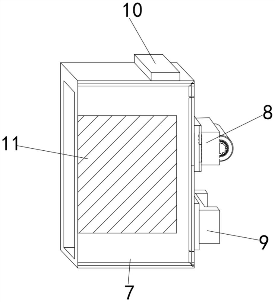
[0031] The overall structure of the lifting door panel 7 is a cuboid hollow structure, and the front end of ...

Embodiment 2

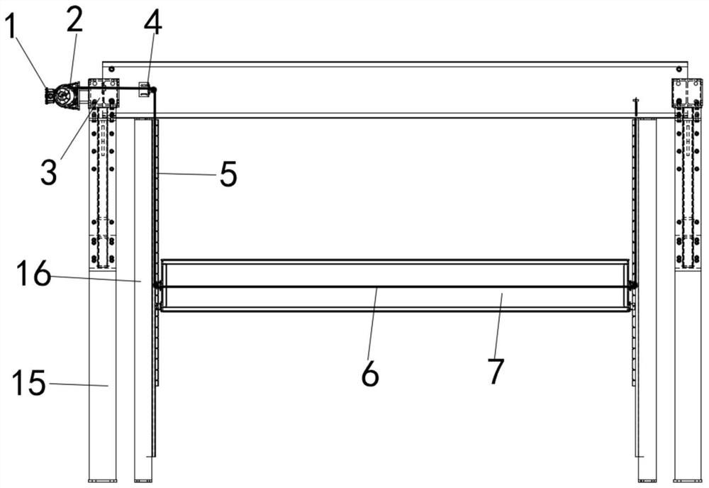
[0033] The upper part of the installation frame 15 is equipped with a guide wheel 3, and the upper part of the installation frame 15 is provided with a motor 1 near the side of the guide wheel 3. The guide wheel 3 can be used to adjust the winding direction of the wire rope 6, and the motor 1 can be used to drive the drum 2 to rotate , so that the wire rope 6 completes the winding or releasing operation.

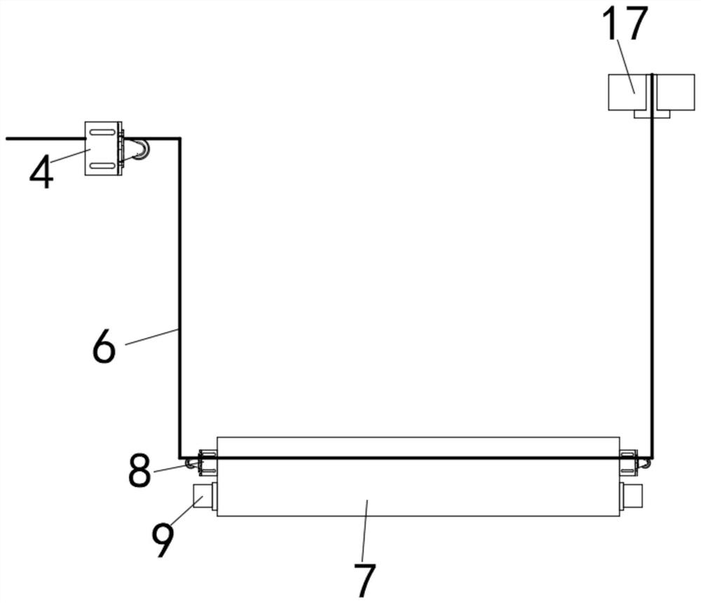
[0034] The motor 1 and the drum 2 are connected by a belt drive. The other side of the guide wheel 3 is provided with a pulley seat 4. The use direction of the wire rope 6 can be adjusted by using the pulley seat 4. The drum 2 drives the wire rope 6 to be rewound and released, so that the wire rope 6 The lifting door panel 7 can be driven to carry out the upgrading adjustment operation.

[0035] The outer surface of the upper end of the lifting door panel 7 is fixedly equipped with rubber pads 10, and the quantity of the rubber pads 10 is two groups. By using the setting of ...


PUM


Abstract

The invention discloses a lifting frame with rollers. The equipment comprises a mounting frame and a lifting door plate, two sets of fixing rods are fixedly mounted on the inner side of the mounting frame, a lifting door plate is movably mounted between the two sets of fixing rods, and the fixing rods and the lifting door plate are movably connected through lifting guide rails. A steel wire rope used for lifting operation is installed in the middle of the inner side of the lifting door plate in a penetrating mode, and a hanging rod is fixedly installed on the outer surface of one end of the steel wire rope. The guide wheel, the pulley seat and the lifting pulley form a pulley guide structure, so that the lifting direction of the steel wire rope is adjusted, the steel wire rope can replace a traditional chain or gear type transmission structure to conduct lifting adjustment operation on the lifting door plate, and therefore the stability of the lifting frame in the using process is improved; in addition, the roller and the steel wire rope form a steel wire type lifting structure, so that the device has the advantages of being simple in structure, low in manufacturing cost and high in automation degree, can be connected with a system operation platform for operation, and is convenient to use.

Description

technical field [0001] The invention belongs to the technical field of parking equipment, in particular to a lifting frame with rollers. Background technique [0002] The lifting rack with rollers is a kind of lifting rack used in the process of parking the vehicle to control the parking space. After the car passes through the magnetic induction loop, the door can be automatically raised. After entering and parking the car, When the car is stored by scanning the code or other methods, the door is automatically closed, and the garage car picker will place the car in the set area. [0003] Patent No. CN209942317U discloses a lifting frame structure with hinged compensation, which belongs to the technical field of three-dimensional garages and includes a lifting body for carrying vehicles. The front and rear ends of the lifting body are fixedly installed or integrally provided with brackets. The support includes a lifting arm and a lifting beam, the upper end of the lifting ar...

Claims


Application Information

Patent Timeline
Patent Type & Authority Applications(China)
IPC IPC(8): E01F13/04
CPCE01F13/042E01F13/048
Inventor 刘政权廖翔宇朱凯鲁能文万德梁凡潘玲
Owner 湖南湘商智能科技有限公司
Why Eureka
Try Eureka