Brushless motor controller power-on protection detection circuit and power-on protection detection method thereof

A brushless motor and detection circuit technology, which is applied in the direction of electronic commutation motor control, control system, measurement of current/voltage, etc., can solve the problems of easy burnout when power on, long detection and protection time, burnout of the controller, etc., and achieve The effect of avoiding burnout, speeding up protection time, and improving reliability and effectiveness

Pending Publication Date: 2020-11-13
ZHEJIANG LINIX MOTOR
View PDF0 Cites 4 Cited by
  • Summary
  • Abstract
  • Description
  • Claims
  • Application Information

AI Technical Summary

Problems solved by technology

[0003] The present invention provides a method to speed up the power-on detection and protection time to solve the current situation of the existing brushless motor controllers such as long power-on detection and protection time, easy to burn out at the moment of power-on, and unable to reliably and effectively protect the controller, so as to avoid power-on detection and protection. Instantaneous controller burnout phenomenon occurs, brushless motor controller power-on protection detection circuit and power-on detection protection method to improve the effectiveness of brushless motor controller protection

Method used


Image

  • Brushless motor controller power-on protection detection circuit and power-on protection detection method thereof
  • Brushless motor controller power-on protection detection circuit and power-on protection detection method thereof
  • Brushless motor controller power-on protection detection circuit and power-on protection detection method thereof

Examples


Embodiment 1

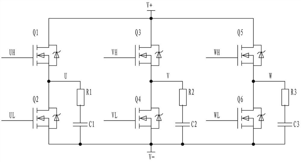
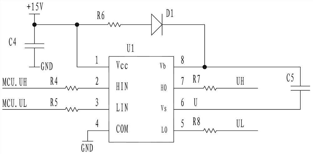
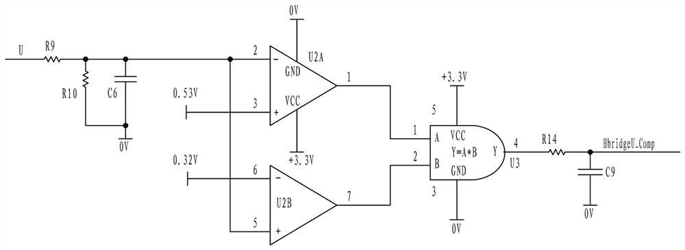
[0026] figure 1 , figure 2 , image 3 , Figure 4In the illustrated embodiment, a power-on protection detection circuit for a brushless motor controller includes a controller main circuit for driving and controlling the three-phase winding of the brushless motor. The main circuit of the controller adopts a three-phase half-bridge circuit structure, and the control The main circuit of the device is composed of six FETs. The positive terminal of the power supply of the three-phase half-bridge circuit is electrically connected to the positive terminal of the 24V DC power input, and the negative terminal of the power supply of the three-phase half-bridge circuit is electrically connected to the negative terminal of the 24V DC power input. The gate network of the effect tube is respectively connected to the HO function pin and the LO function pin of the three pre-driver integrated chips. The three pre-driver integrated chips are powered by +15V power supply and charged by the bo...

Embodiment 2

[0028] figure 1 , figure 2 , image 3 , Figure 4 In the shown embodiment, a brushless motor controller power-on protection detection method includes the following protection monitoring steps:

[0029] A1. The MCU chip controls the three pre-area integrated chips to send a conduction pulse to the upper transistors of the three half-bridges of the first FET, the third FET and the fifth FET, and the upper transistor will be turned on for a short time. At this time, the bootstrap capacitor C5 will flow part of the leakage current to the first FET, the third FET and the fifth FET through the Vb function pin and the VS function pin of the pre-area integrated chip U1 through the bootstrap circuit. The source stages of the upper transistors of the three half-bridges, the source stages of the upper transistors of the three half-bridges are also the U, V, and W terminals of the winding; the three source terminals are due to the existence of their respective RC series circuits, The...


PUM


Abstract

The invention discloses a brushless motor controller power-on protection detection circuit and a power-on protection detection method thereof. A main current loop of the controller adopts a three-phase half-bridge circuit composed of six field effect transistors. The power supply positive electrode end of the three-phase half-bridge circuit is electrically connected with the 24V direct-current power supply input positive electrode; the power supply negative electrode end of the three-phase half-bridge circuit is electrically connected with the 24V direct-current power supply input negative electrode; the gate networks of the six field effect transistors are respectively connected to the HO function pin ends and the LO function pin ends of the three pre-drive integrated chips; each pre-drive integrated chip is powered by a + 15V power supply and charged by a bootstrap capacitor, and an HIN function pin and an LIN function pin of each pre-drive integrated chip are electrically connectedwith an MCU. UH, VH and WH function pin and an MCU. UL, VL and WL function pin of the MCU chip respectively. The power-on detection protection time is reduced, the phenomenon that the controller is burnt out at the moment of power-on is avoided, and the protection effectiveness of the controller is improved.

Description

technical field [0001] The invention relates to a brushless motor controller, in particular to a brushless controller power-on circuit and a power-on detection and protection method of the brushless motor controller used in rail transit, subway, automobile and other industries. Background technique [0002] When the existing brushless motor controller is designed, considering the cost and industry factors, most of the time when the controller is powered on, the main power circuit of the brushless motor controller performs a self-test circuit. Or use software to detect whether the main circuit is over-current, but this detection method has a long delay time and cannot protect the circuit faster. In addition, both traditional methods also have a certain proportion of controllers that will burn out at the moment of power-on, especially after the controller has been used for a long time, some devices cannot reach the original safety performance after aging due to individual diff...

Claims


Application Information

Patent Timeline
Patent Type & Authority Applications(China)
IPC IPC(8): G01R31/52G01R31/58G01R19/165H02P6/00
CPCG01R19/1658G01R31/52G01R31/58H02P6/00
Inventor 金冠军朱美臣周杨洋
Owner ZHEJIANG LINIX MOTOR
Why Eureka
Try Eureka